


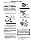
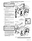
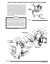
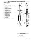
FILL CA
VITY WITH
SAE 10
NON–DETERGENT
MOT
OR OIL
Fig
33–2
39
68
8
71
8
75
18
14
58
69a
69
69b
73
18
25
70
57
22
41
43
42
63
LUBRICATE
LIBERALLY
P
ACK
WITH GREASE
LIBERALL
Y P
ACK
WITH GREASE
LIBERALL
Y P
ACK
WITH GREASE
01580
60
44
33
32
30
307–758
33
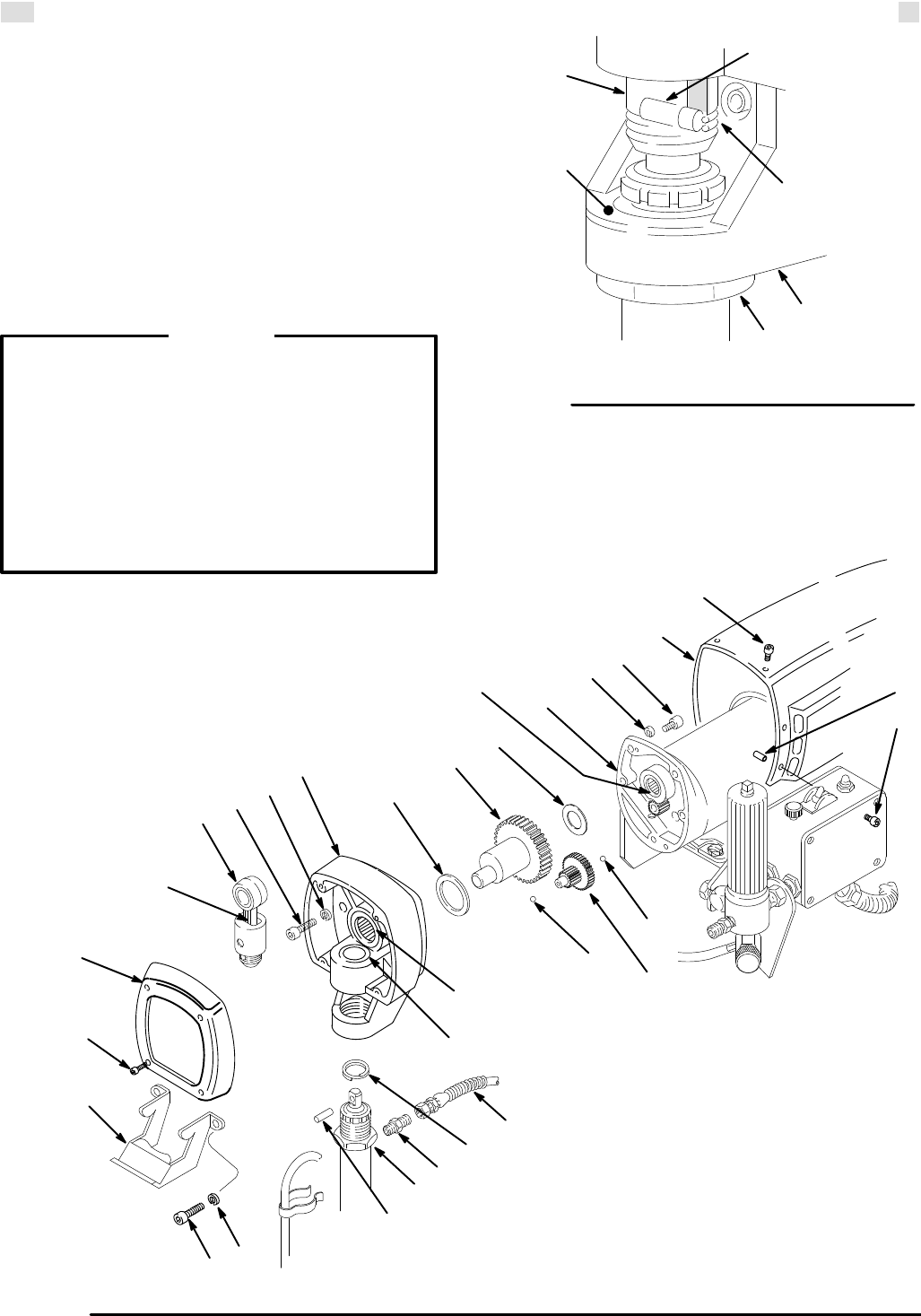
DRIVE
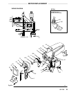
HOUSING, CONNECTING ROD & CRANKSHAFT REPLACEMENT
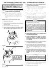
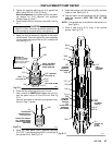
14. Screw
the displacement pump about 3/4 of the way
into
the drive housing (73). Hold the pin (43) up to the
pin hole in the connecting rod assembly (70) and
continue screwing in the pump until the pin slides
easily into the hole. Back off the pump until the top
threads
of
the pump cylinder are flush with the face of
the
drive housing and the outlet nipple
(39) is facing
back.
Push the retaining spring (42) into the groove
all the way around the connecting rod. Tighten the
locknut
(41) very tight – about 70 ft-lb (95
N.m) – with
a 1-3/4 in. open end wrench and a light hammer
.
See
Fig
33–1 and 33–2.
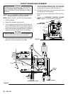
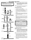
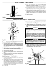
Be sure the retaining spring (42) is firmly in the
groove all the way around, to prevent the pin (43)
from
working loose due to vibration.
See Fig 33–1.
If
the pin works loose, it or other parts could break of
f
due to the force of the pump action. These parts
could
be projected through the air and result in seri
-
ous
bodily injury or property damage, including dam
-
age
to the pump connecting rod or bearing housing.
WARNING
15. Reinstall
the remaining parts.
42
70
43
73
Fig 33–1
FACE
OF
BEARING
HOUSING
41
TORQUE TO
70 ft-lb (95 N.m)