


24
307–758
GENERAL REP
AIR INFORMA
TION
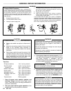
Pressure
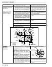
Relief Procedure
To
reduce the risk of serious bodily injury
, including fluid in
-
jection,
splashing fluid or solvent in the eyes or on the skin,
or injury from moving parts or electric shock, always
follow
this procedure whenever you shut off the sprayer, when
checking
or servicing any part of the spray system, when in
-
stalling,
cleaning or changing
spray tips, and whenever you
stop
spraying.
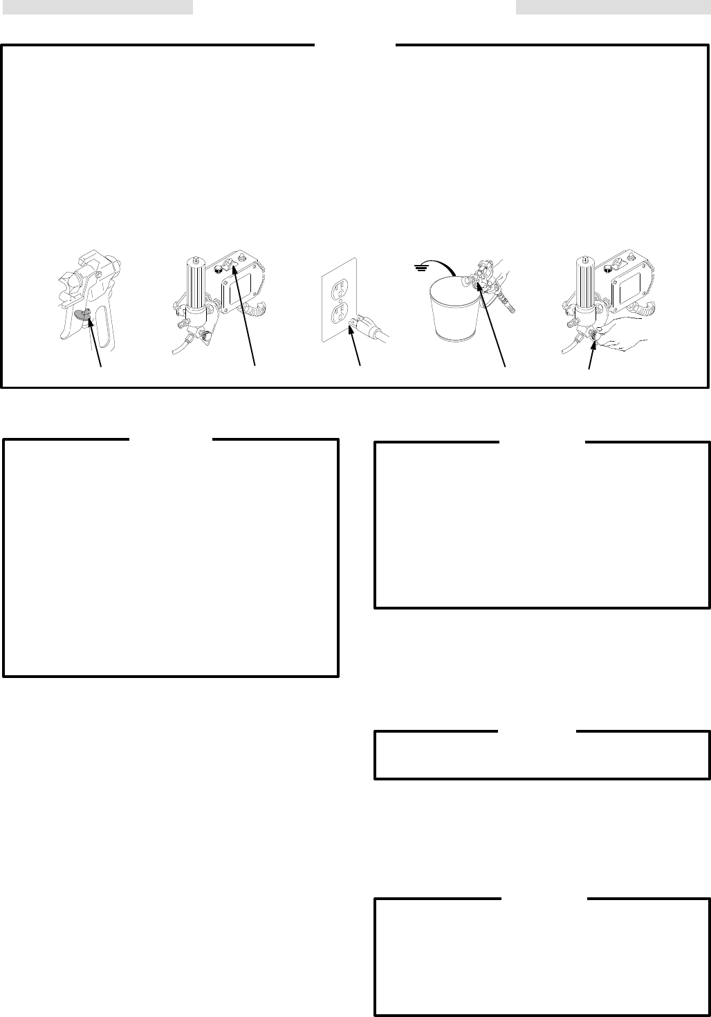
1.
Engage the gun safety latch.
2.
Turn the ON/OFF switch to OFF.
3.
Unplug the power supply cord.
4.
Disengage
the gun safety latch. Hold a metal part of the
gun
firmly to the side of a
grounded metal pail, and trig
-
ger
the gun to relieve pressure.
5.
Engage the gun safety latch.
6. Open the pressure drain valve, having a container
ready
to catch the drainage. Leave the valve open until
you
are ready to spray again.
If you suspect that the spray tip or hose is completely
clogged,
or that pressure
has not been fully relieved after fol
-
lowing
the steps above,
VER
Y SLOWL
Y loosen the tip guard
retaining
nut or hose coupling to relieve pressure gradually
,
then
loosen completely
. Now clear the tip or hose.
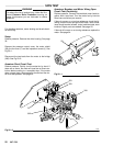
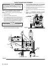
1,5 2 4
6
3
01361
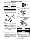
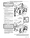
WARNING
To
reduce the risk of a pressure control
malfunction:
D Always use needle nose pliers to disconnect a
wire.
D Mate wire connectors properly. Be sure the flat
blade of the insulated male connector is
centered
in the wrap-around blade of the
female
connector.
D Route wires carefully through the center of the
U-shaped bourdon tube to avoid interference
with the movement of the bourdon tube. Also
avoid interference from the circuit board and
between
the pressure control and cover
.
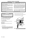
CAUTION
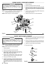
Phillips screwdriver
Small flat blade
screwdriver
Needle nose pliers
Plastic mallet
Adjustable wrench
Adjustable, open-end
wrench
T
orque wrench
1/4 in. hex key wrench
3/16 in. hex key wrench
5/8 in. socket wrench
3/8 in. open end wrench
1/2 in. open end wrench
3/4 in. open end wrench
7/8 in. open end wrench
High quality motor oil
Bearing grease
Tool List
1. Keep all screws, nuts, washers, gaskets, and
electrical fittings removed during repair proce-
dures.
These parts are not normally provided with
re
-
placement
assemblies.
2.
Test your repair before regular operation of the
sprayer
to be sure the problem is corrected.
T
o reduce the risk of serious bodily injury
, including
electric shock, DO NOT touch any moving parts or
electrical parts with your fingers or a tool while in-
specting
the repair
.
Shut off the sprayer and unplug it as soon as you
complete
the inspection.
Reinstall all covers, gaskets, screws and washers
before
operating the sprayer
.
WARNING
3. If the sprayer does not operate properly, review
the repair procedure again to verify that everything
was done correctly. If necessary, see the
Troubleshooting Guide, pages 16–21, to help iden-
tify
other possible problems and solutions.
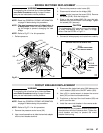
CAUTION
Do
not
run the sprayer dry for more than 30 seconds
to
avoid damaging the pump packings.
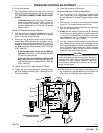
4. Reinstall the motor shield before regular opera-
tion
of the sprayer and replace it if it is damaged. The
cover
directs cooling air around the motor to help pre
-
vent overheating. It can also help reduce the risk of
burns,
fire or explosion; see the
WARNING,
below
.
During operation, the motor and drive housing be-
come very hot and could burn your skin if touched.
Flammable
materials spilled
on the hot, bare motor
could
cause a
fire or explosion. Always have the mo
-
tor
shield in place during regular operation to reduce
the
risk of burns, fire or explosion.
WARNING