


26
307–758
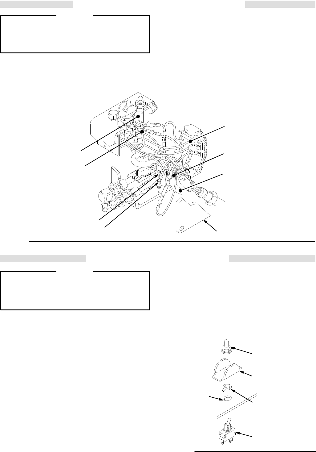
POWER SUPPLY CORD REPLACEMENT
WARNING
To
reduce the risk of serious injury
, follow the illus
-
trated Pressure Relief Procedure warning on
page 24 whenever you are instructed to relieve
pressure.
NOTE: Read the GENERAL REPAIR INFORMATION
on
page 24 before doing this procedure.
NOTE:
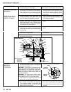
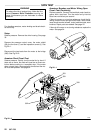
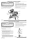
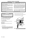
Refer to Fig 26–1 for this procedure.
1.
Relieve pressure.
2.
Remove the pressure control cover (62).
3.
Disconnect
the power supply cord lead from the ON/
OFF
switch (303), the white wire going
to the bridge
(308), and the green wire to the grounding screw
(343).
4. Loosen the strain relief bushing (328). Remove the
power
supply cord (31
1).
5.
Install the new cord (31
1) in the reverse order
.
Fig 26–1
303
01225
311
328
343
327
62
308
01225
306
ON/OFF
SWITCH
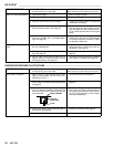
REPLACEMENT
WARNING
To
reduce the risk of serious injury
, follow the illus
-
trated Pressure Relief Procedure warning on
page 24 whenever you are instructed to relieve
pressure.
NOTE: Read the GENERAL REPAIR INFORMATION
on
page 24 before doing this procedure.
NOTE:
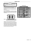
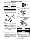
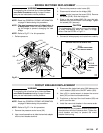
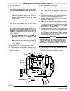
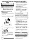
Refer to Fig 26–2 for this procedure.
1.
Relieve pressure.
2.
Remove the pressure control cover (62).
3.
Disconnect the upper terminal wire from the micro-
switch (302) and the two black wires from the
ON/OFF
switch (303). See Fig 26–1.
4. Using a 5/8 in. socket wrench, remove the nut and
rubber
boot (304). Remove the switch guard (305).
5.
Remove the ON/OFF switch (303)
6.
Install the new switch so the internal tab of the anti-
rotation
ring (W) engages with the vertical groove in
the threads of the switch, and the external tab en-
gages
with the blind hole (D) of
the pressure control
box.
7. Install the switch guard (305), aligning the internal
tab
with the groove in the threads.
8.
Powder the inside of the rubber boot (304) with tal-
cum
powder
, then shake the excess out of the
boot.
9. Install
the nut and rubber boot and tighten.
10.
Reconnect all wires.
303
D
W
305
304
Fig 26–2
01228