


307–758 23
BRIDGE TEST
WARNING
To
reduce the risk of serious injury
, follow the illus
-
trated Pressure Relief Procedure warning on
page 24 whenever you are instructed to relieve
pressure.
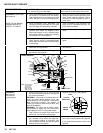
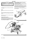
Remove the bridge from the pressure control box and
perform this test to determine if the bridge is functional.
See BRIDGE RECTIFIER REPLACEMENT, page 27.
Use
a continuity tester
, such as multi-meter set on the X1
ohms
scale.
Perform
all tests in the chart. If the bridge fails even one
test,
it must be replaced.
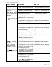
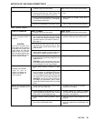
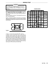
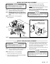
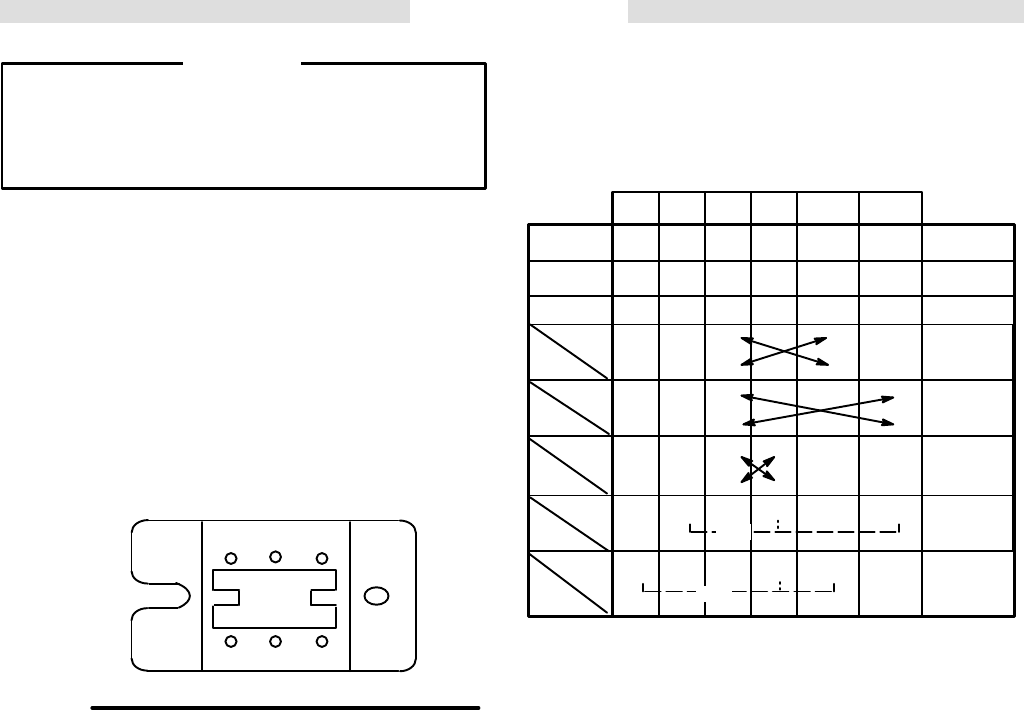
Fig 23–1 shows the position of the wires on the bridge.
Using the chart at the right, connect the meter wires as
indicated
by the black dots for each test,
and then check
the
continuity
.
Fig 23–1
AC1
AC2 G2
G1 –
+
In T
ests 1, 2 and 3, there should be NO continuity
.
In Tests 4, 5 and 6, connect the + and – meter wires as
indicated, check continuity, then switch the meter wire
connections
and check continuity again. Y
ou should get
NO
continuity one way and YES continuity the other way
.
In
T
ests 7 and 8, connect the meter wires as indicated by
the black dots. T
ouch the indicated “G” wire to one meter
wire,
and
then to the other
. Y
ou should get NO continuity
one
way and YES continuity the other way
.
NO DDTEST
1
NO DD
TEST 2
NO DD
TEST 3
YES DD
NO DD
YES DD
NO DD
YES DD
NO DD
YES dD D
NO
YES
dDD
NO
BRIDGE
WIRES
G2 G1 – + AC1 AC2
OR
OR
TEST
5
TEST 6
TEST 4
TEST 7
TEST 8
CONTINUITY