


30
307–758
PRESSURE
CONTROL ADJUSTMENT
This
procedure sets the sprayer to 2750 psi (195 bar)
MAXIMUM WORKING PRESSURE and sets the
overpressurization switch (microswitch) to approxi-
mately
3600 psi (242 bar).
Perform this procedure whenever the pressure con-
trol
assembly is removed and reinstalled or replaced,
or
a new circuit board is installed.
Improper adjustment can cause the sprayer to over-
pressurize
and result in component rupture, fire or ex
-
plosion.
It may also prevent the sprayer from obtaining
the maximum working pressure, resulting in poor
sprayer
performance.
NEVER
try to
increase the sprayer
’
s maximum work
-
ing
pressure of 2750 psi (195 bar) by performing these
adjustments
in any other way
. Normal operation of the
sprayer
at higher pressures may
result in component
rupture,
fire or explosion. T
o perform this adjustment,
however,
the sprayer pressure must
be
temporarily
in
-
creased
above the normal working pressure.
Use
a
new
50 ft (15.2 m) spray hose rated for at least
2750 psi (195 bar) MAXIMUM WORKING PRES-
SURE. A used, under–rated hose could develop a
high
pressure leak or rupture.
WARNING
USE EXTREME CAUTION WHEN PERFORMING THIS ADJUSTMENT PROCEDURE to reduce the risk of a
fluid injection injury or other serious bodily injury which can result from component rupture, electric shock, fire,
explosion,
or moving parts.
WARNING
To
reduce the risk of serious injury
, follow the illus
-
trated Pressure Relief Procedure warning on
page 24 whenever you are instructed to relieve
pressure.
NOTE: Read the GENERAL REPAIR INFORMATION
on
page 24 before doing this procedure.
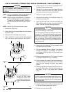
Required tools for adjustment procedure
3/8 in. nut driver or 3/8 in. socket wrench
1/4 in. open end wrench
7/16 in. open end wrench
0 – 5000 psi, oil-filled test gauge, Part No. 102–814
Pail of clean water
Mineral spirits
NEW 3000 psi (210 bar) high pressure spray hose,
Part No. 223–541
1.
Relieve pressure.
2. See the above list of tools and equipment needed.
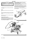
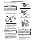
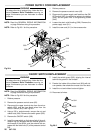
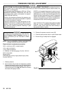
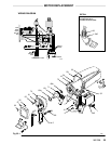
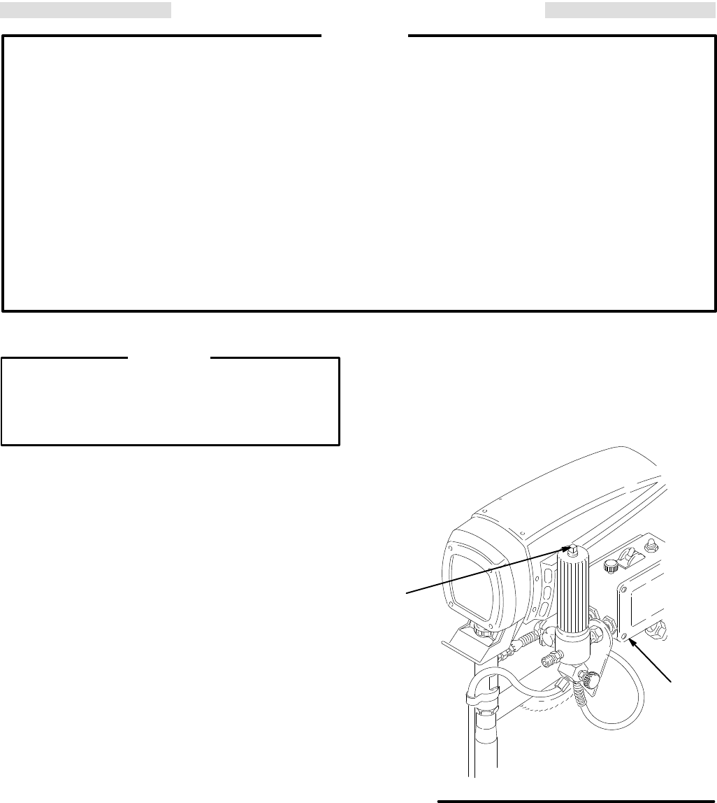
Remove
the plug (A) from the top of the fluid filter and
install
the fluid-filled pressure gauge. See Fig
30–1.
Connect the gun to the new test hose and connect
the
hose to the sprayer outlet.
3.
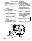
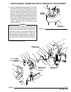
Remove the pressure control cover (62).
4. Place
the pump suction tube in a pail of clean water
.
5. Be
sure the gun safety latch is engaged.
A
Fig 30-1
62
01566