


18
307–758
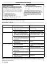
MOTOR
WON’T OPERA
TE
TYPE
OF PROBLEM
WHAT
T
O CHECK
If check is OK, go to next check
WHA
T T
O DO
When check is not OK refer to this column
Condition
B
(continued)
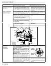
Both
lamps of
f
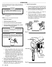
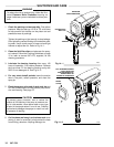
6. Check
motor thermal cutout switch. Connect
volt meter to TP6 female and TP9 female.
Plug
in sprayer and turn on. Meter should read
105
to 125 V
AC.
T
urn of
f and unplug sprayer
.
6. Allow
motor to cool. Correct cause of over
-
heating.
If switch remains open after
motor
cools, check continuity between TP9 fe-
male
and TP10
with ohmmeter
. If open, re
-
place
motor
.
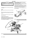
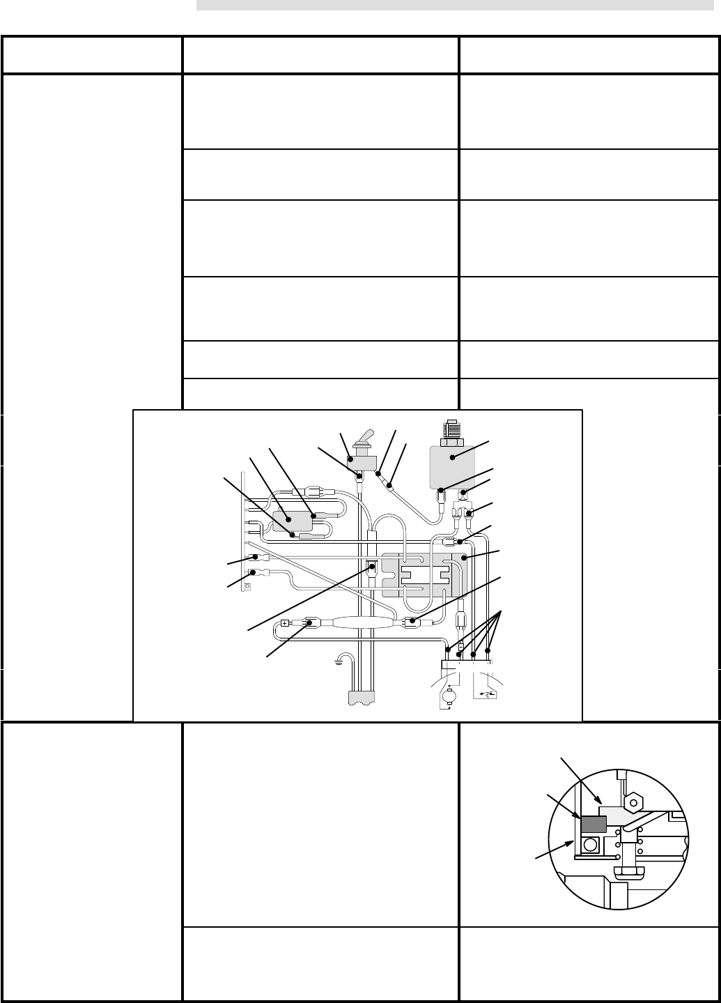
REFER TO THE WIRING
DIAGRAM BELOW TO
IDENTIFY TP POINTS.
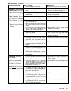
7. Check microswitch (302). Reconnect TP6
connectors.Connect
volt meter to TP15 male
and
TP4. Meter should read 50–125 V
AC.
7. Clean microswitch male terminals. Re-
place loose or damaged terminals. Se-
curely
reconnect leads.
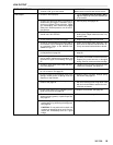
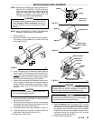
8. Visually
inspect microswitch (302) button. Ad
-
justment stud should not depress button
when fluid pressure is zero. Depress button
with
small screwdriver; audible click
indicates
microswitch
is in normal position.
8. Microswitch is faulty
. Return sprayer for
repair.
9. Check
microswitch (302)
continuity with ohm
meter.
Be sure sprayer is unplugged!
Meter
should
read zero ohms with no fluid pressure
in
the sprayer
.
9. Microswitch is faulty
. Return sprayer for
repair.
10.Check all terminals for damage or loose fit.
Reconnect TP6 connectors.
10.Replace damaged terminals and recon-
nect securely.
11.Check
circuit board (72) by substituting with
a
good
board. See page 28.
11.
Replace circuit board. See page 28.
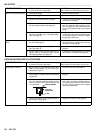
Condition
C
Red
lamps on,
Clear lamp of
f
Unplug sprayer!
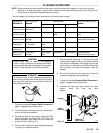
1. Check circuit board (72) by removing from
box
without
disconnecting wires; see page 28
for
removal procedure.
WARNING: Removing circuit board while still
wired over–rides optical detector which may
cause
sprayer to over–pressurize, if
microswitch
does not function properly. Turn sprayer on
ONLY
long enough to check lamp condition,
then
shut
of
f immediately
.
WARNING: To reduce risk of electric shock,
handle board by edges only! Do not allow any
metal
objects to come in contact with board!
Plug
in and turn on sprayer
. Clear lamp should
be
on now
. T
urn of
f and unplug sprayer
.
1.
Replace circuit board. See page 28.
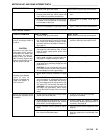
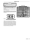
2. Check bourdon tube flag and detector posi-
tion. Reinstall circuit board (see page 28).
Turn pressure setting to maximum; flag
should extend less than half way into optical
detector
slot from the bottom.
2. Perform pressure control adjustment to
see
if that corrects problem. See page 30.
If not, replace bare pressure control. See
page
29.
.
CIRCUIT
BOARD
OPTICAL
DETECTOR
FLAG
AC1
AC2
G1
G2
_
+
WHITE
BLUE
YELLOW
RED
GREEN
BLACK
WHITE
GROUND
WIRE
BLACK
POWER SUPPLY CORD
THERMAL SWITCH
MOTOR
WIRING DIAGRAM
NOTE: These leads have
interchangeable
connections:
TP9 and TP10
TP13 and TP14
TP15 and TP16
MOTOR LEADS
TP3
TP4
TP10
TP9
308
TP8
309
306
TP2
303
TP1
TP15
302
TP16
TP14
TP13
TP6
TP7