


Installation
313526J 15
Installation
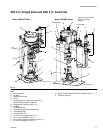
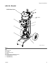
General Information
Accessories are available from Graco. Make certain all
accessories are adequately sized and pressure-rated to
meet the system’s requirements.
F
IG
. 1, F
IG
. 2, and F
IG
. 6 are only guides for selecting
and installing system components and accessories.
Contact your Graco distributor for assistance in design-
ing a system to suit your particular needs.
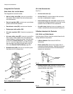
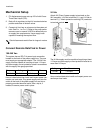
Location
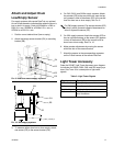
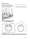
Attach a lifting sling at the proper lift spots. Lift off the
pallet using a crane or a forklift.
Position the ram so the air controls are easily accessi-
ble. Ensure that there is enough space overhead for the
ram to raise fully. (See Dimensions, page 34.)
Using the holes in the ram base as a guide, drill holes
for 1/2 in. (13 mm) anchors.
Ensure that the ram base is level in all directions. If nec-
essary, level the base using metal shims. Secure the
base to the floor using 1/2 in. (13 mm) anchors that are
long enough to prevent the ram from tipping.
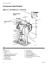
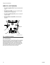
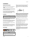
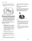
Grounding
Pump: use a ground wire and clamp. Loosen grounding
lug locknut and washer. Insert one end of supplied
ground wire into slot in lug and tighten locknut securely.
Connect other end of wire to a true earth ground. See
F
IG
. 8.
Air and fluid hoses: use only electrically conductive
hoses with a maximum of 500 ft. (150 m) combined
hose length to ensure grounding continuity. Check elec-
trical resistance of hoses. If total resistance to ground
exceeds 29 megohms, replace hose immediately.
Air compressor: follow manufacturer’s recommenda-
tions.
Spray gun/dispense valve: ground through connection
to a properly grounded fluid hose and pump.
Fluid supply container: follow local code.
Object being sprayed: follow local code.
Solvent pails used when flushing: follow local code.
Use only conductive metal pails, placed on a grounded
surface. Do not place the pail on a nonconductive sur-
face, such as paper or cardboard, which interrupts
grounding continuity.
To maintain grounding continuity when flushing or
relieving pressure: hold metal part of the dispense
valve firmly to the side of a grounded metal pail, then
trigger the valve.
Reference numbers and letters in parentheses in
the text refer to the callouts in the figures.
NOTICE
Always lift supply system at proper lift locations (see
F
IG
. 1, F
IG
. 2, and F
IG
. 6). Do not lift in any other way.
NOTICE
The equipment must be grounded. Grounding
reduces the risk of static and electric shock by provid-
ing an escape wire for the electrical current due to
static build up or in the event of a short circuit.
F
IG
. 8
ti8250a