


Supply System Operation
313526J 23
Remote DataTrak Setup
The remote DataTrak display unit comes fully assem-
bled. Use the following instructions and figure to con-
nect remote DataTrak to the supply system.
The system requires either 100-240 Vac, 50/60 Hz
input, or 24 Vdc to the power supply. Ensure that the
main disconnect rocker switch is set to OFF (O). Con-
nect power to the DataTrak unit as detailed in Connect
Remote DataTrak Units to Power, page 16.
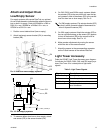
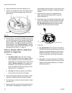
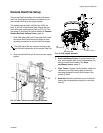
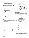
1. Feed CAN cable (HB) and D-Sub cable (HA) under
the remote DataTrak bracket and attach to corre-
sponding connectors on remote DataTrak display.
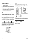
2. Snap remote DataTrak unit to mount on ram supply
system.
3. Drum Low/Empty Sensor: If system has this fea-
ture, attach sensor cable to the corresponding con-
nector on the D-Sub harness. See Drum
Low/Empty Sensor, page 15.
4. Light Tower: If system has this feature, attach the
connector on the light tower cable to the corre-
sponding connector on the D-Sub harness. See
manual 312493.
5. Solenoid: Attach the connector on the D-Sub har-
ness to the corresponding connector on the sole-
noid (X).
The CAN cable (HB) can connect to either of the
two CAN style connectors on the remote DataTrak.
F
IG
. 14: D200, D200s, and D60 supply systems
X
HA
HB
BF
ti10431a
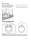
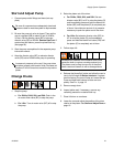
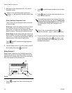
F
IG
. 15: S20 supply systems
X
HA
HB connector
BF
connector
r_cm9hlb_313526_6a