


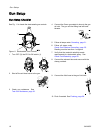
Gun Setup
To reduce the risk of a skin in-
jection injury, always follow the
Pressure Relief Procedure, page 27,
before removing or installing the spray tip, air
cap, or tip guard.
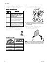
11. The fluid output and pattern width depend
on the size of the spray tip, the fluid
viscosity, and the fluid pressure. Use the
Spray Tip Selection Chart, page 62, as a guide
for selecting the appropriate spray tip for your
application.
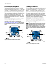
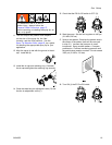
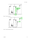
12. Align the spray tip tab with the groove in the air
cap. Install the tip.
13. Install the air cap and retaining ring. Orientate
the air cap and tighten the retaining ring securely.
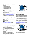
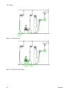
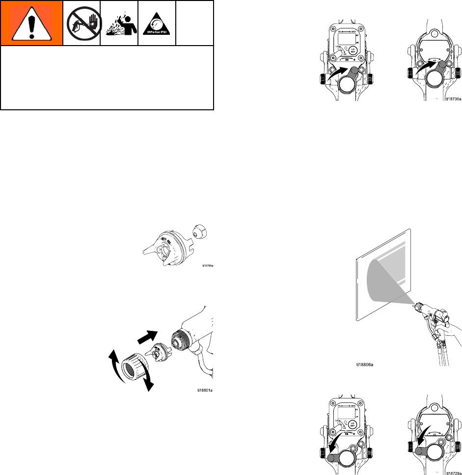
14. Close the atomizing air adjustment valve (G) and
the fan air adjustment valve (F).
15. Check that the ES On-Off switch is OFF (O).
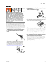
16. Start the pum
p. Set the fluid regulator to 400 psi
(2.8 MPa, 28
bar).
17. Spray a test
pattern. Examine the particle size in
the center o
f the pattern (tails will be removed
in step 21)
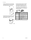
. Increase the pressure in small
increment
s. Spray another pattern. Compare
particle s
ize. Continue increasing pressure until
the partic
le size remains constant. Do not exceed
3000 psi (2
1 MPa, 210 bar).
18. Turn ON (I) the ES On-Off switch.
3A2495C 19