


16 308-084
ELECTRICAL TESTS
The
performance of
the spray gun is directly af
fected by
the condition of the electrical components contained
inside
the gun. The electrical tests below can
be used to
determine
the condition of the
power supply (40) and the
resistor
stud (2) as well as the continuity
of the electrical
path
between the components.
Use
megohmmeter 218–979 (see
ACCESSORIES
) and
an
applied voltage of 500 volts to complete these
electri
-
cal
tests. Connect the leads as shown.
Remove the gun from the manifold and bracket, as
instructed on page 18, before performing the electrical
tests.
WARNING
To
reduce the risk
of sparking, which could cause
fire,
explosion, or electrostatic shock
and result in
serious
bodily injury
, do not use the megohmmeter
in the hazardous area. Remove the gun from the
hazardous
area before testing it.
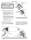
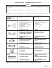
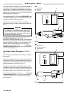
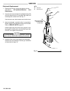
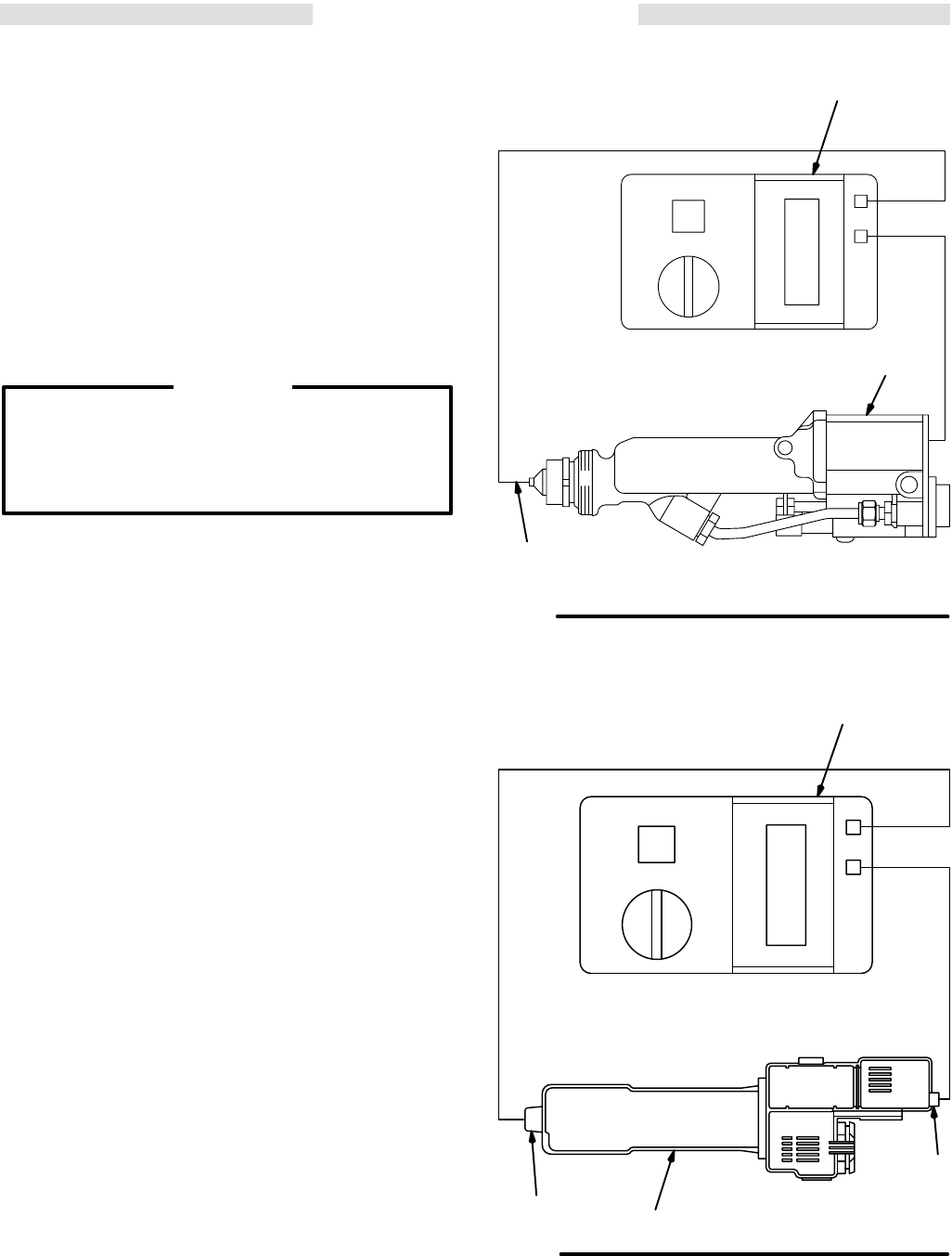
Test Gun Resistance (See Fig 11 )
Measure
the resistance between the end of the
electrode
(28) and the gun body (39). The resistance should be
between 329 to 401 megohms. If the resistance is out-
side the specified range, go to the next test. If the
resistance is correct, refer to the Electrical
Troubleshooting Chart on page 15 for other possible
causes
of poor performance.
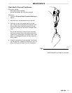
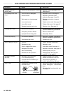
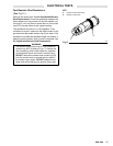
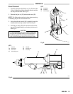
Test Power Supply Resistance (See Fig
12 )
Remove the power supply (40) from the gun body (39).
See
page 25.
Measure
the resistance from the power supply’
s ground
contact
point (EE) to the contact inside of the power
sup
-
ply seal (40d)
[the conductive rubber contact may be
slightly
recessed into the seal]
. See Fig 12 .
The resistance should be 297 to 363 megohms. If the
resistance
is outside the specified range,
the power sup
-
ply
is defective and must be replaced. If the resistance
of
the
power supply is correct, proceed to the next test.
If you still have problems, refer to the Electrical
Troubleshooting Chart for other possible causes of
poor performance, or contact the nearest authorized
service
agency
.
Fig 1
1
KEY
A Megohmmeter
28 Electrode
39 Gun
Body
28
A
39
0440
Fig
12
KEY
A Megohmmeter
EE Ground
Contact Point
40
Power Supply
40d Seal
40
EE
A
40d
0441