


8 308-084
INSTALLATION
Check
the Electrical Grounding
(See Fig
7 )
WARNING
Proper electrical grounding of every part of your
system is essential. For your safety , read the
warning section, FIRE, EXPLOSION, OR
ELECTROSTATIC SHOCK HAZARD , on page
3. Ground the system as explained there. Then
check
your system as explained below
.
1. Completely turn off the air and fluid supplies to the
gun.
2. Have a qualified electrician check the electrical
grounding
continuity of the spray gun and air hose.
a. With the
electrically conductive air hose con-
nected and properly grounded, use a
megohmmeter to measure the resistance
between the gun manifold and a true earth
ground.
Use an applied voltage of 500 minimum
to
1000 volts maximum.
b. If the resistance is greater than 2 megohms*,
check the tightness of the ground connections,
and be sure the air supply hose ground wire is
connected to a true earth ground. If the resis-
tance is still greater than 2 megohms*, replace
the
air supply hose.
* If you are using the red colored hose, resis-
tance
should not exceed 100 ohms.
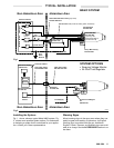
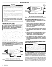
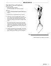
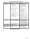
Fig 7
Megohmmeter
See
ACCESSORIES to
order
Gun
Manifold
True Earth
Ground
Grounded
Air Hose
0436
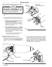
Install the Fabric Cover (See Fig 8 )
1. Install a fabric cover over the front of the gun and
slide
it back to
cover the exposed tubing and hoses at
the back of the manifold. See ACCESSORIES
sec
-
tion.
2. Cut
a small slit in the cover and route the two exhaust
tubes
outside the robot
arm or reciprocator
. This en
-
ables
you to monitor the exhaust tubes
for the pres
-
ence of any paint or solvent. See Check for Fluid
Leakage
on
page 12. Strap down the exhaust tubes
to
prevent them from moving around.
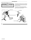
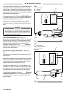
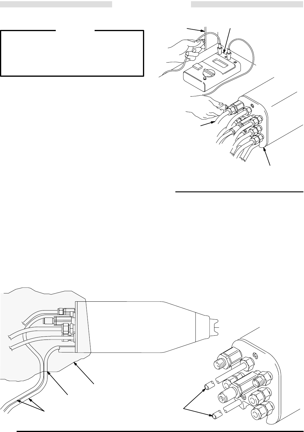
Fig
8
0437
Fabric
Cover
Slit
Exhaust T
ubes
0438
Exhaust T
ubes