


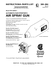
6 308-084
INSTALLATION
WARNING
Installing and servicing this equipment requires
access
to parts which may cause electrostatic shock
or
other serious bodily injury if work is not performed
properly.
D Do not install or service this equipment unless
you
are trained and qualified.
D Be sure your installation complies with National,
State
and Local codes for the installation of elec
-
trical
apparatus in a Class
I
, Group D Hazardous
Location.
D Check and follow all local safety and fire codes,
NFPA
33, NEC 504 and 516, and OSHA standard
1910.107.
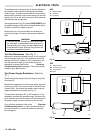
Ventilate the Spray Booth
WARNING
To
prevent hazardous concentrations of toxic
and/or
flammable vapors, spray only in a properly venti-
lated spray booth. Never operate the spray gun
unless
ventilation fans are operating.
Electrically interlock the gun air supply with the ventila-
tors
to prevent gun operation without ventilating fans
op
-
erating. Check and follow all National, State, and Local
codes
regarding air exhaust velocity requirements.
High
velocity air exhaust will decrease the operating ef
fi-
ciency of the electrostatic system. The minimum allow-
able air exhaust velocity is 60 feet/minute (19 linear
meters/minute).
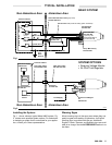
Install the Gun Mounting Bracket
Attach
the
mounting bracket to the robot or reciprocator
.
See
the
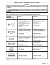
ACCESSORIES
section for the mounting brack
-
et and mount extension options and refer to Fig 3 and
Fig
4 for mounting positions.
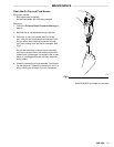
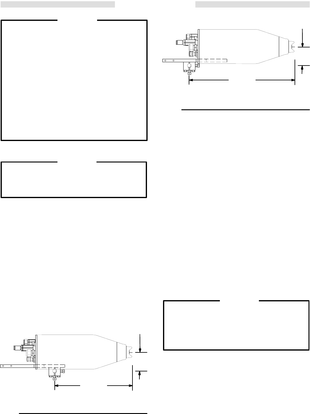
Fig 3
01876
FRONT MOUNTING POSITION
PRO
4600 Gun
with Slotted Shroud
P/N 235–894
2.3
in.
(58 mm)
8.8 in.
(235 mm)
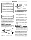
Fig
4
01876
BACK MOUNTING POSITION
PRO
4600 Gun
with Standard Shroud
P/N 235–893
2.3
in.
(58 mm)
12 in.
(304 mm)
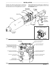
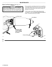
Install the Gun and Manifold (See Fig 5 )
1. Remove the air cap nut/air cap assembly and slide
the
shroud of
f the gun.
2. Connect the gun to the manifold by tightening the
three socket head cap screws; use the ball end
wrench (46), supplied. Make sure the o-ring is in
place
on the manifold.
3. Slide
the gun
and manifold along the dovetail until the
button head screw bottoms against the mounting
bracket.
4. Secure
the gun to the mounting bracket with the but
-
ton head screw , using the ball end wrench (46).
Tighten
the two mounting bracket setscrews.
5. Slide
the shroud onto the gun and secure it by tight
-
ening
the air cap nut onto the gun barrel. T
ighten
the
nut
just enough so that the air cap is snug
but can still
be
turned.
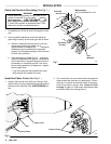
Connect the Air, Fluid, and Optional Fiber
Optic Lines (See Fig 6 )
WARNING
To reduce the risk of electrostatic shock or other
serious
injury
, the turbine air supply hose must be
electrically
connected to
a true earth ground.
Use
Only
Graco Electrically
Conductive Air Supply
Hose
and connect the
hose ground wire to a
true
earth
ground.
See
the
ACCESSORIES
section to
order Graco Electri
-
cally
Conductive Air Supply Hose. This hose
and the gun
have special left-hand threads to prevent connecting
another
type of
air supply hose to the gun turbine air inlet.
Connect
the air
, fluid, and optional fiber optic
lines to the
gun
manifold as shown in Fig 6 . Before connecting the
fluid
line, blow it out with air and flush it with solvent.
Use
solvent
that is compatible with the fluid being sprayed.