


22 308-084
SERVICE
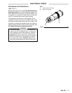
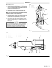
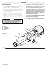
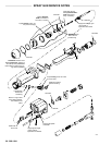
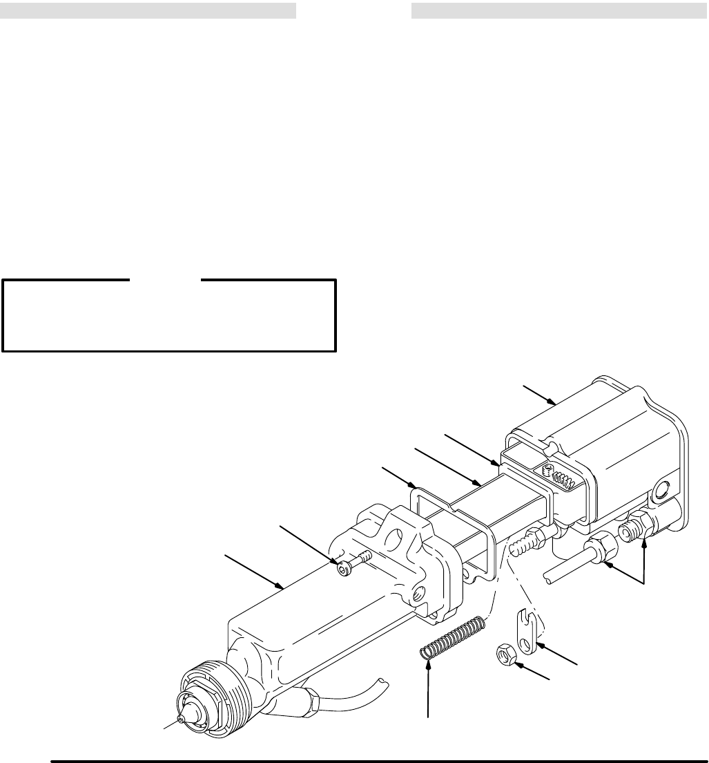
Barrel Installation
1. Be
sure the gaskets (23 & 40a) and spring (1
1) are in
place.
See Fig 20 . Replace if damaged.
2. Place
the barrel (10) over the power supply (40) and
onto
the gun body (39). Make sure the fluid rod spring
(11)
is seated properly
.
3. Tighten the three socket head cap screws (15)
oppositely
and evenly with the ball end wrench (46).
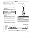
Tighten the cap screws to 18 in-lbs (2 N Sm)
MAXI-
MUM
(about a half turn past snug).
DO NOT
over
tighten.
CAUTION
To
avoid damaging the gun,
DO NOT
over
tighten
the cap screws (15). Tighten the screws to 18 in-
lbs (2 N Sm)
MAXIMUM
(about a half turn past
snug),
using the wrench (46) supplied only
.
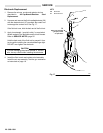
4.
Install the fluid tube back into the fluid fitting (21).
5. Install
the actuator arm (29) and jam nut (25), with the
jam
nut assembled flush to the end of the rod.
There
should be about a 1/16 in. gap between the ac
-
tuator
arm (29) and the nut on the fluid shaft. When
the gun is triggered, the electrode needle should
draw back 3 to 4 mm. If necessary , adjust the jam
nuts
to obtain these dimensions.
The
jam nut
must be tightened securely to prevent it
from
loosening during operation.
6. T
est the gun resistance as instructed on page 16.
Fig 20
KEY
10 Gun
Barrel
11 Spring
15
Cap Screws
21
Fluid T
ube Fitting
23 Gasket
25
Jam Nut
29
Actuator Arm
39
Gun body
40
Power Supply
40a Gasket
0457
10
15
23
40
40a
39
21
29
25
11