


308-08425
SERVICE
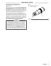
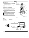
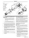
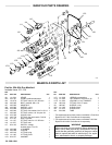
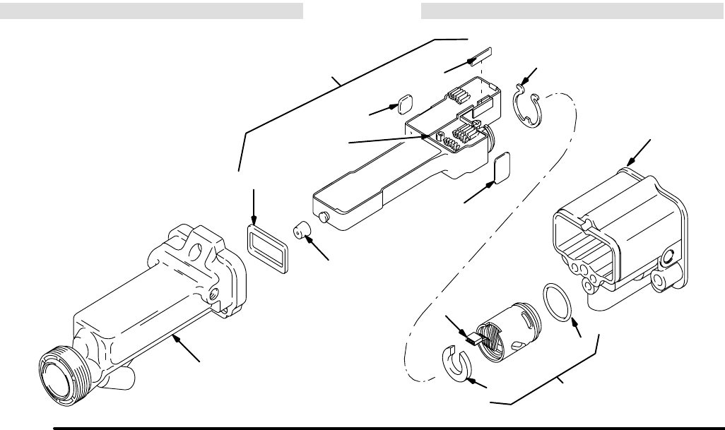
Fig
23
KEY
F 3-wire
Connector
G Potentiometer
10
Gun Barrel
13
Retainer Ring
27 Alternator
27a O-Ring
27b Cushion
39
Gun Body
40
Power Supply
40a Gasket
40b Pad
40c Pad
40d Seal
40e Cushion
39
13
27a
27b
40a
40
27
F
10
40b
40c
40e
G
40d
0450
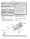
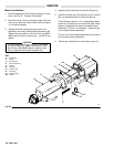
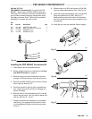
Power Supply Removal and Replacement
REPAIR
NOTES:
a. T
o avoid a loss in electrostatic performance,
inspect the gun handle’
s power supply cavity
for dirt or moisture. Clean the cavity with a
clean, dry rag.
b.
Do not expose the seal (40d) or o-ring (27a) to
solvents as solvents will damage them.
1. Remove
the barrel as described in
Barrel Removal
.
2.
Grasp the power supply (40) with your hand. With a
gentle
side-to-side motion, being careful not to dam
-
age
the power supply
, pull the power supply free
from
the
gun handle (39), then pull it straight out.
3. Inspect the power supply for any physical damage.
Check
the electrical
resistance as instructed in
Test
Power Supply Resistance. If needed, replace the
power
supply
.
Before installing the power supply, inspect the seal
(40d) for any damage or swelling; replace if neces-
sary. Also, make sure the gaskets/pads (40a–40e)
are
in place.
4. Lubricate
the
o-ring (27a) and insert the power sup
-
ply
in the gun handle.
5. Install
the barrel on the handle as
described in
Barrel
Installation.
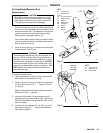
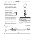
Power Supply Adjustment
The KV HI/LO switch, on the back of the gun manifold,
enables you to switch between full voltage and a lower
voltage
output. The lower voltage is factory set at 60 kV
,
but
can be adjusted between 45 and 80 kV
.
To adjust the low voltage setting, use a small blade end
screw driver to turn the potentiometer (G), clockwise
to
increase
the voltage or counterclockwise to decrease it;
fully
clockwise is 80 kV
, fully counterclockwise is 45 kV
.
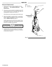
Turbine Alternator Removal and
Replacement
NOTE: Replace turbine bearings after 2,000 hours of
operation.
See your authorized Graco representative.
1. Remove the power supply from the gun handle as
described
at left.
2. Squeeze the two ends of the retaining ring (13)
together and carefully pull the alternator (27) away
from the power supply (40) until the wire connector
(F)
disengages. See Fig 23 .
3. Use an ohmmeter to test the turbine alternator coil.
Measure
the resistance between the two outer termi
-
nals of the 3-wire connector (F). Resistance should
be
3 to 5 ohms. If the
reading varies from this value,
replace
the alternator
.
4. Connect
the 3-wire connector to the 3 prongs in the
power
supply
. Push the alternator (27) onto the pow
-
er supply (40) until the retaining ring (13) engages
with
the alternator
.
5. Install the power supply in the gun handle as
described
at left.