


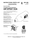
308-0847
INSTALLATION
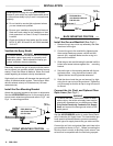
To
ensure a dry
, clean air supply to the gun, install an air
line
filter and an air and water separator on the air
lines.
Dirt and moisture can ruin the appearance of your fin-
ished
workpiece and can cause the gun to malfunction. A
combination air filter/moisture separator is shown in
the
ACCESSORIES
section.
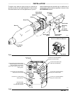
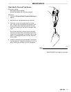
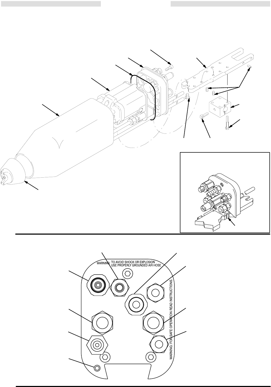
Socket
Head
Cap Screws
Manifold
O-Ring
Spray Gun
Shroud
Mounting
Plate
Dovetail
Set Screws
Button
Head
Screw
Air Cap/Air
Cap Nut
01877
Hex Head
Cap Screws
Mounting
Block
Square Head
Set Screw
Fig
5
0453
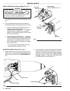
BACK
V
IEW
OF
M
ANIFOLD
INSTALLED
ON
M
OUNTING BRACKET
Set Screw
Fig
6
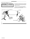
TURBINE
ATOM
PAINT
KV
HI/LO
EXH
F.O.
FAN
CYL
MAX WRP
AIR AND FLUID
100 PSI (7 BAR)
0322
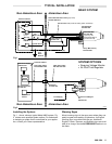
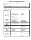
Connect
4’ of
1/4” ID tube
Connect 1/4” OD tube between
fitting and control module
Connect Graco Fiber Optic
Cable
(see Accessories)
Connect 3/8” OD tube between
fitting and control module
Connect 1/4” OD tube between
fitting and control module
Connect Graco Grounded Air Hose
between fitting & control module
(left-hand thread)
. Connect the
ground
wire on the air hose to a true
earth
ground.
Connect 3/8” OD tube between
fitting and control module
Connect a 1/4” npsm swivel
fitting paint line
Shroud Exhaust
1/4” OD x 4’ tube
(included with manifold)