


10ą307-638
OPERATION
Install the Fluid Nozzle and Air Cap
WARNING
To
reduce the risk
of serious bodily injury
, including
splashing in the eyes or on the skin or electric
shock, always follow the Pressure Relief Proce-
dure on page 9 before installing, or removing the
fluid
nozzle/air cap assembly
.
1. See Instruction Manual 307–803 for air cap con-
sumption
and fluid nozzle flow rate information. The
fluid output and pattern shape depends on the fluid
nozzle
size, fluid viscosity
, and fluid pressure.
2. Remove
the old air cap and fluid nozzle as instructed
in Clean the Air Cap and Fluid Nozzle, steps 1
through
4.
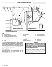
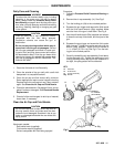
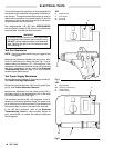
3.
Push
the pin housing (83) into the slot (A) on the front
of
the gun until it bottoms out. See Fig 4.
4.
Push the locking pin (84) into the housing (83).
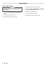
5. Turn
the locking pin (84) to the unlocked position, and
screw
the
new fluid nozzle (13) onto the gun. See Fig
5.
6. T
urn the locking pin (84) to the locked position to lock
the
fluid nozzle (13) in place.
7. Carefully install air cap assembly. Avoid bending
electrode
(12). T
ighten the retaining nut so
it is snug,
allowing
the air cap
to turn with resistance. If too tight,
the
spray pattern will be distorted.
Adjust the Spray Pattern
Follow
these steps to establish the correct fluid flow and
air
flow
.
DO NOT
turn the ES ON–OFF lever to ON yet:
1. Adjust the fluid flow for the appropriate flow rate by
using
the
fluid pressure regulator installed in the fluid
line.
Check the fluid nozzle chart in manual 307–803
for
the appropriate flow rate for the air cap. Start with
the
lowest rate shown
and increase it until you get the
desired
flow rate.
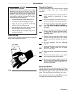
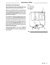
2. For fine adjustment, use the adjusting knob (Z) lo-
cated
at
the rear of the gun. See Fig 2. T
urn the knob
clockwise to reduce the amount of fluid being
sprayed and counterclockwise to increase the
amount
of fluid being sprayed.
3. Choose the correct size air cap for the type of fluid
being
sprayed and the pattern desired.
4. Be
sure the fan adjusting knob (AA) is closed (turned
fully
clockwise).
5. Use
an air pressure regulator to adjust the degree of
atomization.
Always use the lowest air pressure pos
-
sible
for the most ef
ficiency.
NOTE: A minimum of 2.8 bar (40 psi) air supply at the
gun is required to ensure full voltage from the
power supply. The gun may be operated at a
lower air pressure/voltage if required, but may
lose
some electrostatic wrap.
6. First, complete all the checks under the Operating
Checklist on page 9. Then turn the ES ON–OFF
lever to ON. When spraying, the
ES indicator light
should
glow
, indicating the electrostatic charge.
7. Use the
fan adjusting knob
to change the shape of
the spray pattern. Turn the knob counterclockwise
for a wide pattern and clockwise for a solid, round
pattern. When increasing to a wide, flat pattern, it
may be necessary to increase the supply of fluid to
the gun to maintain the same amount of coverage
over
a large area.
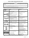
NOTE: See
the
Spray Pattern T
roubleshooting Chart
on
page 13 to correct spray pattern problems.
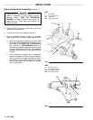
Fig 4
Fig 5
KEY
A Slot
83 Pin
Housing
KEY
13
Fluid Nozzle
14
Air Cap Assembly
84
Locking Pin
A
83
14
13
Locked
Position
Unlocked
Position
DETAIL
DETAIL
84
84