


16 307-638
ELECTRICAL TESTS
The performance of the spray gun is directly affected by
the condition of the electrical components contained inĆ
side the gun. The electrical tests below can be used to
determine the condition of the power supply (5) and the
resistor stud (16) as well as the continuity of the electriĆ
cal path between the components.
Use megohmmeter 218-979 (see ACCESSORIES)
and an applied voltage of 500 volts to complete these
electrical tests. Connect the leads as shown.
ăWARNINGĂ
To reduce the risk of sparking, which could cause
fire orexplosion andresult in seriousbodily injury,
DO NOT use the megohmmeter in the hazardous
area. Remove the gun from the hazardous area
before testing it.
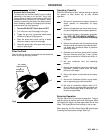
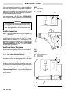
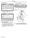
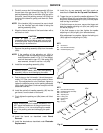
Test Gun Resistance
NOTE: Check the resistancewith the gun triggered and
untriggered.
Measure the resistance between the end of the elecĆ
trode (12) and the gun air fitting (2a). See Fig 7. The reĆ
sistance should be between 115-152 megohms. If the
resistance is outside the specified range, go to the next
test. If th e resistance is correct, refer to the Electrical
Troubleshooting Chart on page 15 for other possible
causes of poor performance.
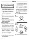
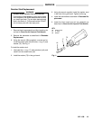
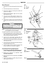
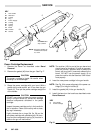
Test Power Supply Resistance
Remove thepower cartridge(3) from thegun handle (2).
See Power Cartridge Replacement.
Remove the turbine alternator (3a) from the power supĆ
ply (5). See Turbine Alternator Removal.
Measure the resistance from the center prong (EE) in
the power supply to the contact spring (5c) on the other
end of the power supply. See Fig 8.
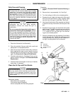
The resistance should be 95-122 megohms. If the reĆ
sistance is outside the specified range, the power supĆ
ply isdefective and mustbe replaced.If theresistance of
the power supply is correct, proceed to the next test.
If you still have problems, refer to the Electrical
Troubleshooting Chart for other possible causes of
poor performance, or contact the nearest authorized
service agency.
Fig 7
KEY
A Megohmmeter
2 Gun Handle
2a Air Fitting
12 Electrode
Fig 8
KEY
A Megohmmeter
EE Connector Center Prong
5 Power Supply
5c Contact Spring
2a
12
A
A
5c
5
EE
2