


6ą307-638
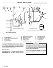
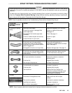
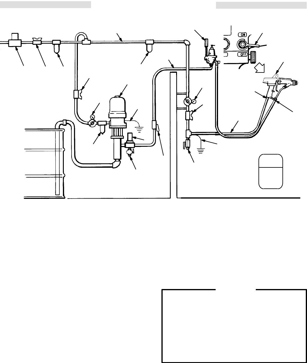
TYPICAL INSTALLATION
KEY
A Main
Air Supply Line
B V
entilation Fan Interlock Solenoid V
alve
C
Main Air Supply Shutof
f V
alve (bleed–type)
D
Air & W
ater Separator
E
Pump Air Supply Shutof
f V
alve (bleed–type)
F
Air Line Lubricator
G
Air Pressure Regulator
H Pump
J
Pump Ground Wire
K
Fluid Filter
L
Fluid Supply Line Shutof
f V
alve
M
Fluid Pressure Regulator
N
Fluid Supply Line
O
Air Filter (5 micron)
P
Air Supply Line
Shutof
f V
alve (bleed–type)
Q
Spray Gun Ground Wire
R
Grounded Air Supply Hose
S
Electrostatic Spray Gun
T
ES On–Of
f V
alve Lever
U
Air Line Drain V
alve
V
Fluid Drain V
alve
W
Gun Air Inlet
X
Gun Fluid Inlet
NON–HAZARDOUS
AREA
HAZARDOUS AREA
WARNING
SIGN
BCD
O
A
M
N
H
E
G
F
V
K
L
U
Q
R
G
P
W
S
X
Power
Supply Must Be Interlocked
W
ith Spray Booth Exhaust Fan.
T
J
The Typical Installation shown above is only a guide for
selecting
and installing electrostatic air spray systems. It
is not an actual system design. The particular type and
size
system
for your operation must be custom designed
for your needs. For assistance in designing a system,
contact
your Graco representative.
Warning Signs
Mount warning signs in the spray area where they can
easily be seen and read by all operators. See the
ACCESSORIES
section to order
.
WARNING
Installing and servicing this equipment requires ac-
cess
to parts which may cause electric
shock or other
serious bodily injury if work is not
performed
properly
.
Do not install or service this equipment unless
you are trained and qualified.
Be sure your installation complies with National,
State
and Local codes for the
installation of electrical
apparatus in a Class 1, Group D, Divisions 1 and 2
Hazardous
Location.