


307-638ą7
INSTALLATION
Ventilate the Spray Booth
WARNING
To prevent hazardous concentrations of toxic
and/or
flammable vapors, spray only in a properly
ventilated
spray booth. Never operate the spray
gun unless ventilation fans are operating.
Check and follow all of the National, State and
Local codes regarding air exhaust velocity
requirements.
Check
and follow all local
safety and fire codes and
OSHA standard 1910–107(b)(5)(i).
NOTE: High
velocity air exhaust will decrease the oper
-
ating efficiency of the electrostatic system. Air
exhaust
velocity of 100–150 ft/min (31–46 linear
meters/minute)
should be suf
ficient.
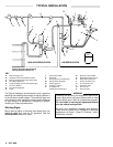
Connect the Air Line (Refer
to the T
ypical
Installation Drawing)
WARNING
To
reduce the risk of
electric shock or other serious
bodily injury, the air supply hose must be electri-
cally
connected to a true earth ground.
Use
Only
Graco Electrically Conductive Air Supply
Hose. This hose, and the gun, have special
threads which prevent using any other type of
hose with the gun. See the ACCESSORIES sec-
tion
to order the hose.
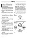
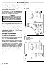
1. Connect
the air supply hose (R) between the air sup
-
ply line and the gun’s air inlet (W).
The gun air inlet
fitting
has a left hand thread.
Connect the air
supply
hose
ground wire (Q) to a true earth ground.
2. Install
an air line filter (O) and an air and water sepa
-
rator
(D) on the air line to ensure a dry
,
clean air sup
-
ply
to the gun. Dirt and moisture can ruin the appear
-
ance of your finished workpiece and can cause the
gun
to malfunction.
3. Install
a bleed–type air regulator (G) on the pump and
gun air supply lines to control air pressure to the
pump
and gun.
4. Install
a bleed–type air shutof
f valve
(C, E, P) on the
main
air line, the pump line, and each gun air supply
line to shut off air to the pump and/or gun(s). Install
an additional bleed–type valve on each pump air
supply line to relieve air trapped between this valve
and
the pump after the air regulator is shut of
f.
WARNING
The
bleed–type air shutoff valve
is required in your
system to relieve air trapped between this valve
and the pump after the air regulator is closed.
Trapped air can cause the pump to cycle unex-
pectedly, which could result in serious bodily in-
jury,
including splashing in the eyes or on the skin
and
injury from moving parts.
5.
Install an air line lubricator (F) as close to the pump
(H) as possible.
Connect the Fluid Line (Refer
to the T
ypical
Installation Drawing)
1. Before
connecting the fluid line (N),
blow it out with air
and flush it with solvent. Use solvent which is com-
patible
with the fluid to be sprayed.
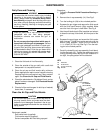
2. Install
a fluid regulator (M) on the fluid line to control
fluid
pressure to the gun.
3. Install
a fluid filter (K) and drain valve (V) at the
pump
outlet.
WARNING
The
fluid drain valve
(V) is required in your system
to
assist
in relieving fluid pressure in the displace
-
ment pump, hose and gun; triggering the gun to
relieve pressure may not be sufficient. Install a
drain valve close to the pump’s fluid oulet. The
drain
valve reduces the risk of property damage or
serious bodily injury, including splashing in the
eyes or on the skin and contamination from haz-
ardous
fluids.
4. Connect
the fluid line to the 3/8–18.6(m) gun fluid in
-
let
(X).