


307-638 21
SERVICE
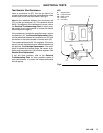
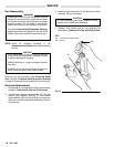
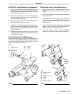
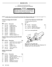
5. Carefully
remove the
fluid needle assembly (45) from
the
rear part of the gun barrel (18). See Fig 15. If the
packing
assembly (45a) or insulator (45g) are still in
the
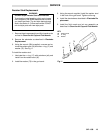
barrel, insert the packing removal rod (59d) into
the
front of the barrel to gently push them out. Refer
to
Fig 16.
NOTE: If
the insulator (45g) is removed, be sure to install
it so the insulator end with holes is facing the
packing
assembly (45a).
6. Wipe
the internal surfaces of the barrel clean with a
soft brush or cloth.
CAUTION
Clean all parts in non–conductive solvent
compatible
with the fluid being used, such as xylol
or
mineral spirits. Use of conductive solvents can
cause the gun to malfunction.
7. Remove
the packing
assembly (45a) from the needle
(45b).
NOTE: If the position of the adjusting nut (45c) is
changed,
install the
adjusting nut to the approxi
-
mate dimension shown in Fig 15. (Final adjust-
ment
will be made in step 15.) If the spring (45f)
was
removed, reinstall it over the nut (45d).
8.
Install the new packing assembly (45a).
CAUTION
Carefully screw needle (45b) into new packing
assembly
(45a) to avoid damaging the seals.
9. Test
the
drag on the fluid needle. It should be approxi
-
mately
2.5–3 lbs (use a small spring scale to meas
-
ure). If the adjustment is out of tolerance, tighten or
loosen
the adjusting
screw on the packing assembly
(45a)
slightly and retest. Continue to
adjust until the
tolerance
is correct.
10. Install the entire fluid needle assembly (45) into the
gun
barrel, from the back of the barrel.
11. Firmly
tighten the packing nut (45e) down until
it bot
-
toms.
CAUTION
When checking the fluid needle movement, DO
NOT move the needle out of the gun barrel more
than
6.35 mm (1/4 in.) to avoid pulling the needle
out of the packing area and damaging the pack-
ings.
12. Install the barrel as described under Barrel
Removal.
13. Install the electrode as described under Electrode
Replacement.
14. Install the air cap assembly and fluid nozzle as
described
in
Clean the Air Cap and Fluid Nozzle
.
15. Trigger
the gun to check the needle adjustment.
The
air should come fully on before the fluid comes on.
Adjust
the needle adjusting nut (45c) until the proper
lead
and lag is achieved.
If
the fluid comes on too soon
, remove the trigger and
back the needle adjusting nut (45c) out (away from
the
barrel) slightly
.
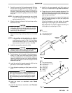
If the fluid comes on too late,
tighten the needle
adjusting
nut (45c) slightly (turn towards barrel).
After
adjustment is complete, tighten
the locking nut
(45d)
against the adjusting nut (45c).
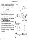
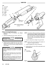
Fig 15
18
45
KEY
18 Gun
Barrel
45
Fluid Needle Assembly
45c
Needle Adjusting Nut
132.7 mm
(5.2 in.)
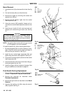
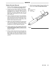
45
45a
45b
45c
45e
45f
45g
Fig
16
KEY
45 Fluid
Needle Assembly
45a
Needle Packing Assembly
45b
Fluid Needle
45c
Adjusting Nut
45d
Locking Nut
45e
Packing Nut
45f Spring
45g Insulator
45c
45d