


24 307-638
SERVICE
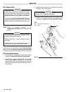
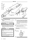
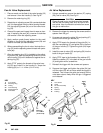
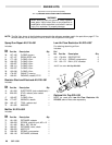
Fan Air Valve Replacement
1. Place
a wrench on the flats of the valve housing (33)
and
remove it from the handle (2). See Fig 20.
2.
Remove the retaining ring (31).
3. Rotate
the air adjusting screw
(34)
counterclockwise
until it is disengaged from the
valve housing threads.
Pull the adjusting screw (34) out of the valve hous-
ing (33).
4. Clean
all the parts and inspect them for wear or dam
-
age. If replacing the seal (40), unscrew it
clockwise
and
remove it from the adjusting screw
.
5. Apply medium grade thread sealant to the small
threads on the end of the adjusting screw (34) and
install
a new seal (left hand thread).
6. When
reassembling the fan
air valve, lubricate the o–
ring
(32)
and the adjusting screw threads with petro
-
leum
jelly
.
7. After
the retaining ring (31) is installed on the adjust
-
ing screw (34), back the adjusting screw out of the
valve
housing (33) until it bottoms out against the re
-
taining ring (31).
8. Apply
PTFE
r
paste to the threads of the valve hous
-
ing (33) and install it in the handle (2). Torque the
housing
(33) to 1.1–1.4 N
S
m (10–12 in–lb).
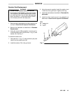
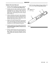
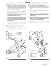
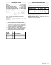
Air
V
alve Replacement
1. Using
a screwdriver
, remove the
retainer (27), spring
(26),
and air valve (25). See Fig 21.
CAUTION
Clean
all parts in non–conductive solvent compat
-
ible
with
the fluid being used, such as xylol or min
-
eral
spirits. Use of conductive solvents can
cause
the
gun to malfunction.
2. Remove
the trigger by removing the screws and the
spacers
from the gun.
3. Unscrew
and remove the guide (24) and packing (47)
from
the front of the gun handle (2).
4. Apply
PTFE tape to the threads of the guide (24). In
-
stall
the new packing (47) and guide (24) in the front
of the gun handle (2). Tighten the guide (24) finger
tight
only
.
5. Install
the new air valve (25) and spring (26) into the
back
of the gun handle (2).
6. Apply
PTFE tape to the threads of
the retainer (27).
Install
the retainer (27) in the back of the gun handle
(2)
and tighten with a screwdriver
.
7.
Reinstall the trigger with the screws and spacers.
8. Squeeze the trigger and tighten the guide (24) just
until
the valve (25) will not return when the trigger is
released.
Then loosen the guide just enough so
the
valve stem returns freely when the gun is triggered
and
released.
Fig 20
Fig 21
KEY
2
Gun Handle
24 Guide
25
Air V
alve Assembly
26 Spring
27 Retainer
47 Packing
KEY
2
Gun Handle
31
Retaining Ring
32 O-Ring
33 V
alve Housing
34
Adjusting Screw
40 V
alve Seal
40
31
32
34
33
25
T
orque to
1.1–1.4 N
Sm
(10–12 in–lb)
26
27
Apply
PTFE
tape
47
24
Apply
PTFE
tape
2
2