


G1021 15" Planer
-13-
Planer Unit
TO MOUNT THE PLANER:
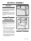
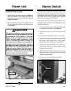
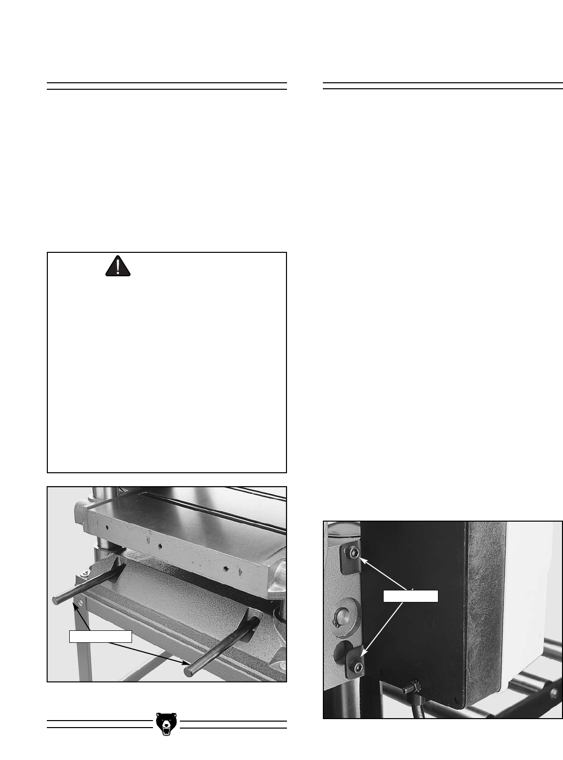
1. Using the lifting handles shown in Figure 4,
place the planer on the stand and align the
four holes in the base over the four mounting
holes in the stand.
2. Secure the planer base to the stand with the
four hex bolts, nuts, washer and fender wash-
ers provided.
Starter Switch
The thermally protected, magnetic switch pro-
tects the motor from overload and the operator in
case power is interrupted. If power is interrupted,
the planer will not turn on when power resumes
without first pressing the ON button.
The switch must be secured to the planer unit.
The cap screws used for this purpose are already
partially screwed in.
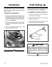
1. Unscrew the cap screws from the planer body
for mounting the switch. See Figure 5.
2. Support the switch and screw the cap screws
back in.
To connect the switch power leads to the motor:
1. Remove the motor junction box cover and slip
the power cord through the cable clamp.
Secure the cable clamp with a screwdriver.
2. Attach the two power leads to the motor ter-
minals according to the wiring diagram sup-
plied with this manual.
3. Attach the grounding terminal (green wire) to
the motor frame via the ground screw located
inside the junction box.
4. Re-attach the motor junction box cover.
Lifting Handles
CAUTION
This planer is relatively heavy and awkward
to handle. We strongly recommend that you
get assistance. It will require at least two
people to lift the planer onto the stand.
Lifting without ample assistance could
result in serious injury and/or damage to
your machine. The planer unit may also be
unstable until it is permanently mounted to
the stand. Use care so the planer unit does
not slide or tip. If placing the planer on a
shop-built stand, ensure that the stand is
stable and designed to carry the weight of
the planer. Always bolt the planer to any
stand including a shop-built stand.
Figure 4. Location of lifting handles.
Figure 5. Starter switch attachment.
Cap Screws