


G1021 15" Planer -23-
Bed Rollers
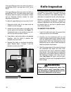
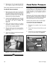
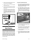
Figure 22. Roller pressure assembly.
Pressure Setscrew
Pressure Spring
Roller
Check Nut
Height Setscrew
4. Remove the springs that are in the holes left
by the setscrews. See Figure 22.
5. Check for any dirt or grit. Clean the springs
and setscrews if dirty.
6. Screw the three regular-pressure setscrews
back in until they are flush with the top of the
head casting.
7. Screw the light pressure setscrew until it is
approximately
1
⁄
4" above the head casting.
The feed chain applies additional tension to
the right side of the outfeed roller, so the
pressure added by the setscrew need not be
as high.
TO ADJUST THE BED ROLLERS:
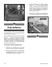
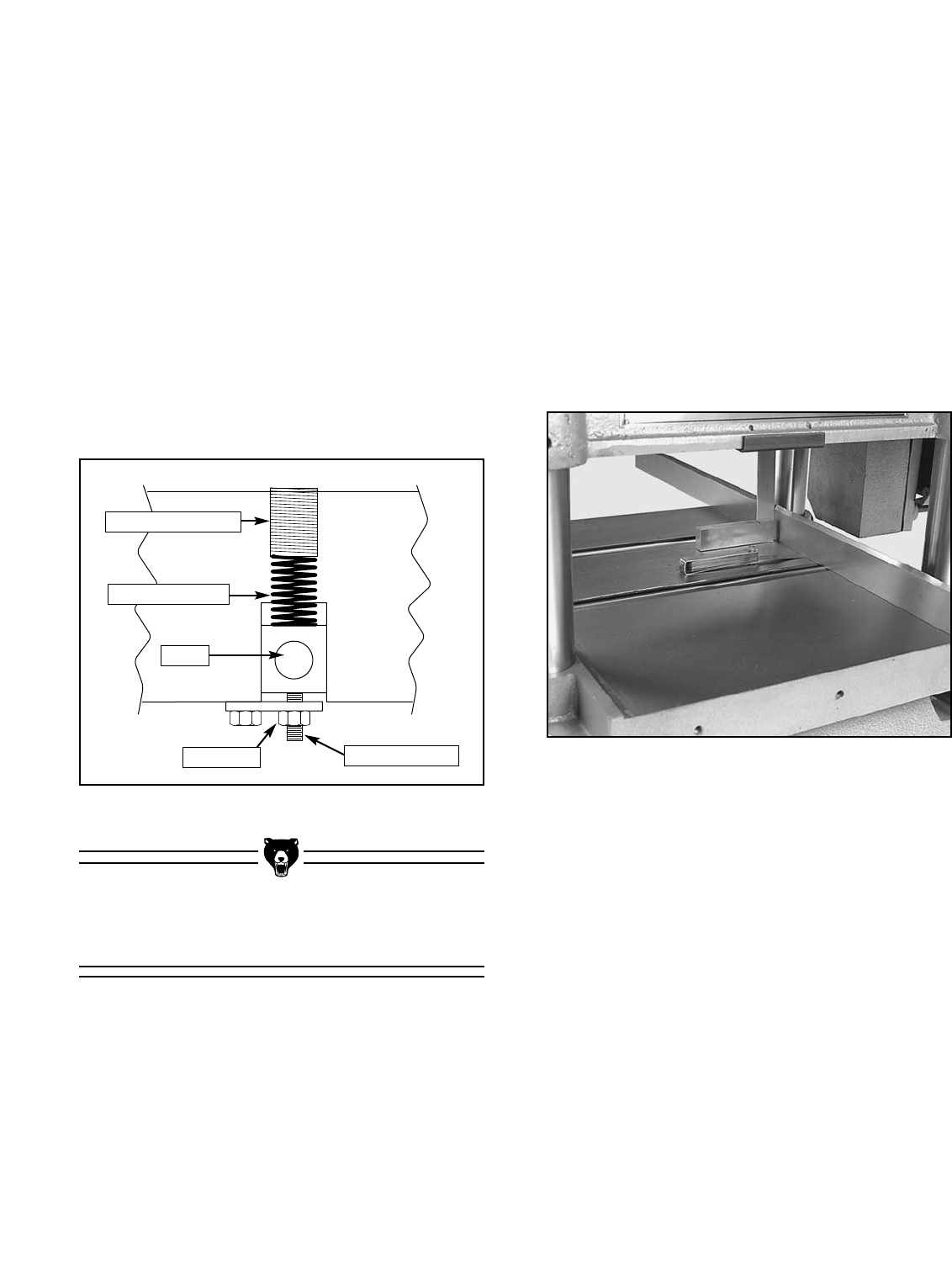
1. Ensure that power is disconnected and lay a
high quality straightedge across both table
rollers. Use a try square to keep the straight-
edge perpendicular to the table.
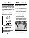
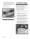
2. Use a feeler gauge to measure the clear-
ance between the bottom of the straight
edge and the table. Ideal clearance is
between 0.002" and 0.005". Measure in sev-
eral places. This measurement must be con-
sistent across the entire table. See Figure
23.
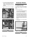
Figure 23. Inspecting bed roller height.
3. Loosen the setscrews on both sides of each
bed roller. See Figure 24.
4. Use a wrench to turn the eccentric shafts
which adjust roller height. Stop turning when
the table rollers are at the proper height.
5. Once your roller heights are correct, re-tight-
en all the setscrews.
6. Check the height of the table rollers. Repeat
steps 1-5 until the bed rollers are properly
set. Spin the bed rollers to ensure free move-
ment.
The bed rollers ease stock movement through
the planer. The height of the bed rollers will vary
depending on the types of wood you will be plan-
ing. When planing rough stock, set the rollers
slightly high to keep the lumber from dragging
along the bed. However, snipe may be unavoid-
able. Smooth lumber should be planed with the
rollers set just above the plane of the table. This
will minimize snipe.