


G1021 15" Planer -25-
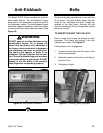
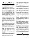
The Model G1021 Planer provides an anti-kick-
back safety feature. The anti-kickback fingers
hang from a rod suspended across the front of
the cutterhead casting. The anti-kickback fingers
should be inspected regularly. Check the fingers
to ensure that they swing freely and easily. See
Figure 26.
Figure 26. Anti-kickback assembly.
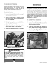
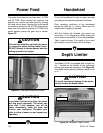
The belt and pulley assembly are on the left side
of the planer. The belts transfer power from the
motor to the cutterhead and then through the
gearbox to the feed rollers. Remove the belt
cover by unscrewing the four flange bolts holding
the cover in place.
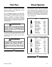
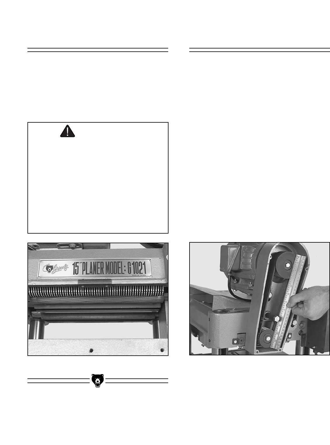
TO INSPECT/ADJUST THE PULLEYS:
Place a metal ruler across the pulleys to check
alignment. The pulleys are aligned if the ruler
crosses them evenly. See Figure 27.
If the pulleys are out of alignment:
1. Loosen the bolts that hold the motor to the
motor mount bracket.
2. Adjust the position of the motor until the pul-
leys are in line.
3. Re-tighten all bolts.
Figure 27. Checking pulley alignment.
WARNING
DO NOT apply oil or other lubricants to the
anti-kickback fingers. Oil or grease will
attract dust and restrict free movement of
the fingers, which could result in damage to
your workpiece, the planer, or possibly seri-
ous injury to the operator or others in the
workplace. Call our Customer Service num-
ber if the anti-kickback fingers do not move
freely when setting up your planer. DO NOT
attempt to use the planer if the anti-kick-
back fingers are not operating properly.
BeltsAnti-Kickback