


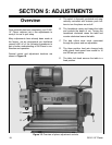
-20- G1021 15" Planer
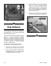
Chip Breaker
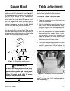
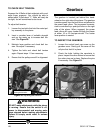
3. Place the gauge block on the table directly
under the cutterhead. Using a one millimeter
(0.05") feeler gauge between the gauge
block and the cutterhead, raise the table
until one of the knives just touches the feel-
er gauge. Rotate the cutterhead manually to
be sure the knife is at bottom dead center.
4. Lock the table by tightening the table lock
knobs.
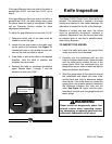
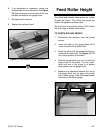
5. Remove the feeler gauge and slide the
gauge block under the chip breaker. See
Figure 17. The chip breaker should just
touch the top of the gauge block. Slide the
gauge block to the opposite end of the chip
breaker and check it in the same manner.
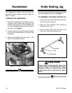
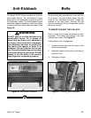
Figure 16. Tightening knives in cutterhead.
4. While holding the position of the knife setting
jig, tighten the gib bolts down again in the
cutterhead. Tighten the bolts evenly from the
outside, working toward the middle. See
Figure 16.
5. Repeat these steps for the other two knives.
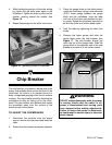
The chip breaker is located on the top side of the
planer and extends down around the front of the
cutterhead. Its function is to prevent tear-out or
deep, unregulated gouging as the knives remove
material. The chip breaker works by breaking the
woodchips as they are being cut by the cutter-
head. The chip breaker also deflects and expels
the woodchips away from the surface of the
board and out of the planer.
TO ADJUST THE CHIPBREAKER:
1. Disconnect the machine from the power
source, remove the dust hood and lower the
table.
2. Ensure that the knives are properly adjusted.
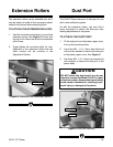
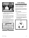
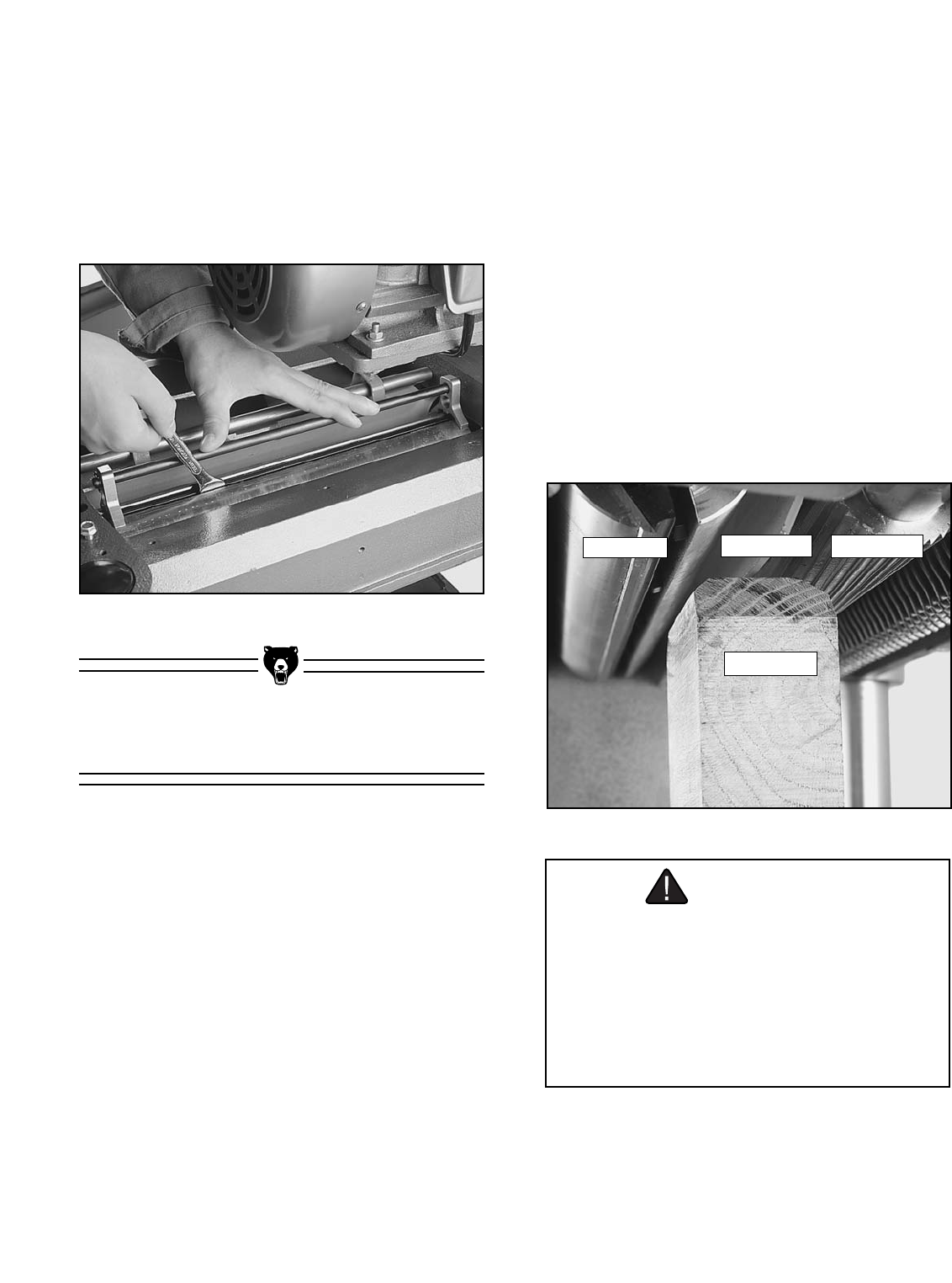
Figure 17. Location of chip breaker assembly.
Gauge Block
Chipbreaker
Infeed Roller
Cutterhead
WARNING
DO NOT make adjustments while the planer
is running. Ensure that the switch is off,
power is disconnected and moving parts
have stopped before making adjustments.
Failure to ensure that power is disconnect-
ed could result in serious injury or electrical
shock hazard.