G0636X 17" Ultimate Bandsaw
-25-
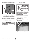
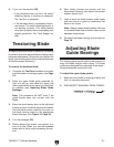
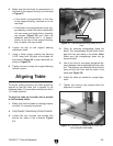
5. Make sure that the blade is perpendicular to
the face of the support bearing, as illustrated
in Figure 27.
—If the blade is perpendicular to the face
of the support bearing, continue on to the
next step.
—If the blade is not perpendicular to the sup
-
port bearing, loosen the lateral adjustment
rod cap screw and guide block assembly
cap screws (
Figure 26) and rotate the
assembly side-to-side until it is perpen
-
dicular to the face of the support bearing,
then re-tighten the cap screws.
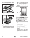
6. Loosen the bolt on the support bearing
adjustment shaft.
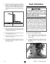
7. Using a feeler gauge, position the bearing
0.016" away from the back of the blade, as
illustrated in
Figure 28, or use a dollar bill, as
shown in Figure 29
.
8. Tighten the bolt to keep the support bearing
locked in place.
Aligning Table
To ensure cutting accuracy, the table should be
aligned so that the miter slot is parallel to the
bandsaw blade. This procedure works best with a
1
3
⁄8" blade installed.
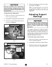
To align the table so the miter slot is parallel
to the bandsaw blade:
1. Make sure that the blade is tracking properly
and that it is correctly tensioned.
2. DISCONNECT BANDSAW FROM POWER!
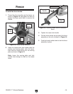
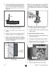
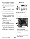
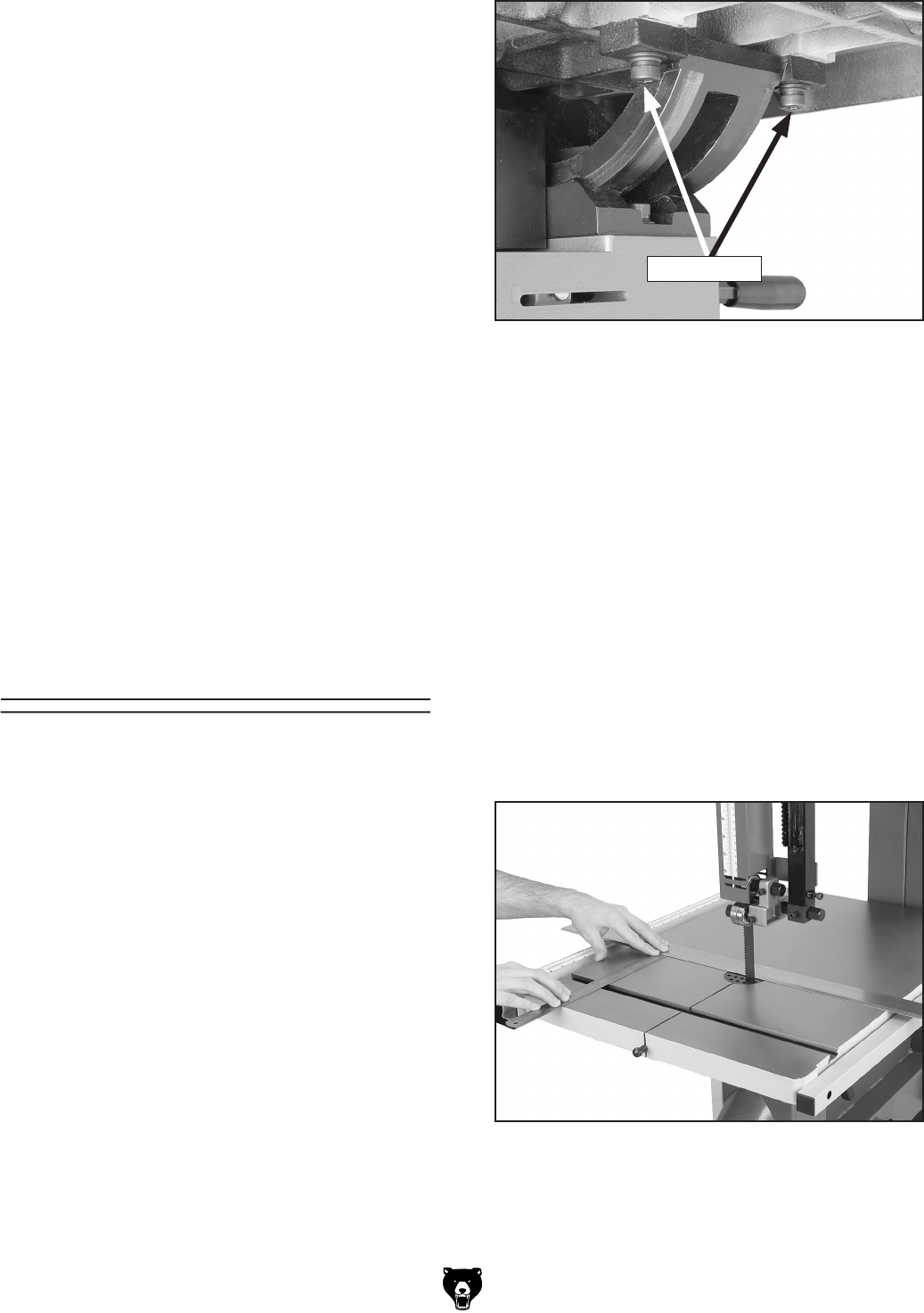
3. Loosen the four trunnion cap screws that
secure the table to the trunnions (
Figure
31).
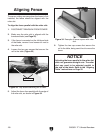
Figure 31. Cap screws securing table to trun-
nion.
4. Place an accurate straightedge along the
blade. The straightedge should lightly touch
both the front and back of the blade.
Note:
Make sure the straightedge does not go
across a tooth.
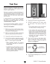
Figure 32. Example of measuring for miter slot
to be parallel with blade.
5. Use a fine ruler to accurately gauge the dis-
tance between the straightedge and the miter
slot. The distance you measure should be the
same at both the front and the back of the
table (
see Figure 32).
6. Adjust the table as needed for proper align-
ment.
7. Tighten the trunnion cap screws when the
alignment is correct.
Cap Screws


