G0636X 17" Ultimate Bandsaw
-29-
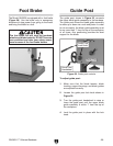
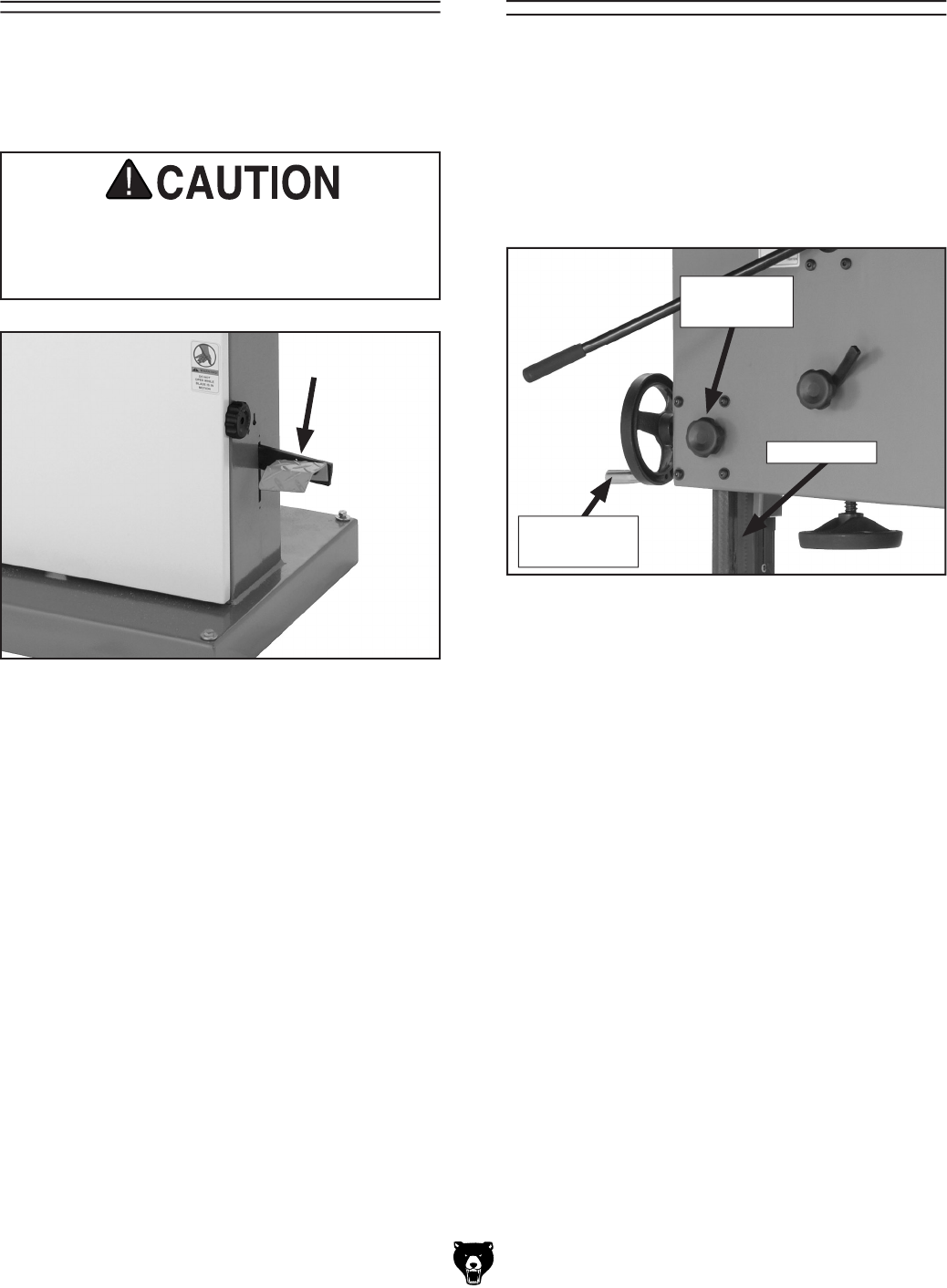
Figure 38. Foot brake location.
The Model G0636X is equipped with a foot brake
(Figure 38). Use the brake only in emergency
situations to stop power from going to the motor
and bring the blade to a halt.
The foot brake will not stop the bandsaw
wheels and blade instantly. DO NOT become
over confident and relax your safety aware
-
ness because of the foot brake feature.
Foot Brake
Guide Post
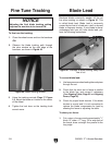
Lock Knob
Guide Post
Handwheel
To adjust guide post:
1. Make sure that the blade tension, blade
tracking, support bearings, and blade guides
are adjusted correctly.
2. Loosen the guide post lock knob shown in
Figure 39.
3. Turn the guide post handwheel to raise or
lower the guide post until the upper blade
guide assembly is within 1" from the top of
the workpiece.
4. Lock the guide post in place with the lock
knob.
Guide Post
Figure 39. Guide post controls.
The guide post, shown in Figure 39
, connects
the upper blade guide assembly to the bandsaw.
The guide post allows the blade guide assembly
to move up or down via a rack and pinion. In order
to cut accurately, the blade guide assembly must
be no more than 1" from the top of the workpiece
at all times—this positioning provides the best
support for the blade.
Guide Post


