


G0449/G0450 37" Drum Sander
-35-
13. Tighten all the lock nuts.
14. Check the height of the drum ends to make
sure they did not move.
—If they did not move, continue to the next
step.
—If they did move, repeat Steps 11-12.
15. Raise the table up until the gauge blocks just
touch the rear drum, as described in Step 7
.
16. Adjust the height of the front drum ends by
loosening the locknuts and sliding the pillow
bearing up or down along the wedge until the
largest size feeler gauge you can fit between
the front drum and gauge blocks at both ends
is 0.015". This will reflect the rear drum depth
of cut.
Note: The 0.015" setting is based off the
suggested depth of cut in the
SECTION
4: OPERATIONS; however, you can set
the front drum between 0.005" and 0.025",
depending on the sandpaper grit size you will
use (ie, coarse grit = larger number; fine grit
= smaller number).
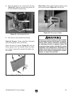
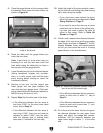
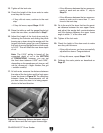
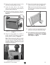
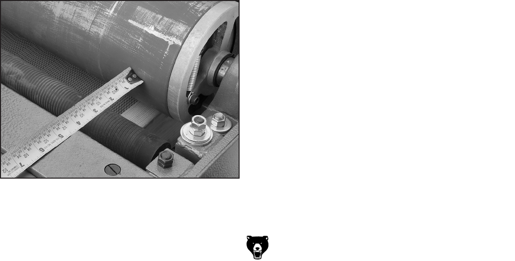
17. At both ends, measure the distance between
the edge of the front drum and the front upper
frame, as shown in
Figure 38. The difference
between these two measurements will tell
you how close the drum is to being perpen
-
dicular to the feed direction.
Figure 38. Measuring distance between edge of
the front drum and the front upper frame angle.
—If the difference between the two measure
-
ments at each end are within
1
⁄8", skip to
Step 19
.
—If the difference between the two measure
-
ments at each end is more than
1
⁄8", con-
tinue to the next step.
18. Go to the end of the drum that has the great-
est distance between the rear upper frame,
and adjust the wedge bolt counterclockwise
until the distance between the upper frame
angle is within
1
⁄8" of the other end.
19. Tighten all the lock nuts.
20. Check the height of the drum ends to make
sure they did not move.
—If they did not move, you have successfully
adjusted the drums. Congratulations!
—If they did move, repeat Steps 17-18.
21. Calibrate the scale pointer as described on
Page 37.