


-38-
G0449/G0450 37" Drum Sander
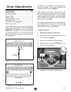
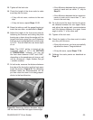
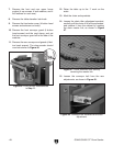
5. Loosen the chain with the adjustable idler
roller sprocket shown in
Figure 43.
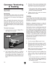
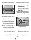
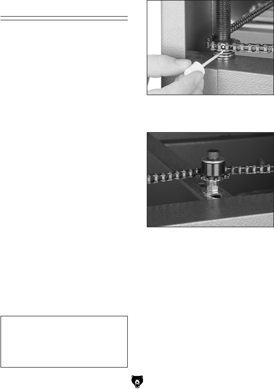
Figure 42. Marking sprocket tooth and chain.
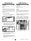
Tools Needed: Qty
Hex Wrench 8mm ..............................................
1
Wrench/Socket 14mm .......................................
1
Flat Head Screwdriver .......................................
1
Chalk, white-out, or paint ..................................
1
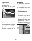
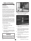
The table lift screws
are connected by a chain
and driven by the table elevation handwheel.
When the chain is removed from a sprocket on
one of the lift screws, that lift screw can adjust
that portion of the table up/down independently to
assist in setting the table parallel to the drums.
Adjusting the table lift screws will only be neces
-
sary if you need to adjust the drum heights more
than allowed at the pillow bearing adjustments,
or if you have removed the table or chain during
a service procedure and you need to reset the
drums parallel to the table.
Each tooth on the sprocket represents 0.006" or
.16mm of table elevation movement. For example,
if the rear of the table was
0.006" low, rotate both
rear table lift screws to the next sprocket tooth in
the same chain position. You can easily rotate the
sprockets from the top of the table lift screws with
a flat head screwdriver.
To adjust the table lift screws:
1. Disconnect power to the sander!
2. Open the side cover.
3. Raise the table up to at least the 1" mark on
the height scale.
4. At the lift screw that needs to be adjusted,
mark the end of a sprocket tooth and the
chain hole where that tooth is meshed, as
shown in
Figure 42.
Table Lift Screws
6. Carefully move the chain off of only the
marked sprocket.
7. Keep track of the marked chain hole and
rotate the sprocket the necessary number of
teeth away from the marked one to meet the
difference in height needed.
8. Fit the chain back over the sprocket, making
sure the new sprocket tooth is inserted into
the marked chain hole.
9. Re-tension the chain and check the new
height setting.
10. Repeat Steps 5–9 as needed until the table
height is parallel to the drums in all four cor
-
ners, and calibrate the scale pointer.
Figure 43. Adjustable idler roller sprocket.
NOTICE
Marking the chain and sprocket locations
will save you a substantial amount of time
when you reinstall the chain. Make sure you
have done this before removing the chain.