


G0449/G0450 37" Drum Sander
-39-
Tools Needed: Qty
Hex Wrench 8mm ..............................................
1
Hex Wrench 5mm ..............................................
1
Hex Wrench 4mm ..............................................
1
Hex Wrench 3mm ..............................................
1
Wrench/Socket 19mm .......................................
1
Wrenches/Sockets 14mm .................................
2
Wrench 13mm ...................................................
1
Wrench/Socket 12mm .......................................
1
Wrench 10mm ...................................................
1
Phillips Head Screwdriver .................................
1
Measuring Tape ................................................
1
Gauge Blocks (see
Page 30) ............................ 2
Feeler Gauge Set ..............................................
1
3 Assistants for Lifting Help ...............................
1
Flashlight or Work Light ....................................
1
Replacing the conveyor belt is a big job and
requires moderate mechanical skill and a fair
amount of patience. For planning purposes,
expect to have your machine out of operation for
at least a few hours.
As you remove hardware to complete these
instructions, we recommend putting all the bolts,
screws, washers, etc. back into the holes from
which they came. This simple habit will take
slightly longer when disassembling the machine,
but it will save you a lot of time and reduce frus
-
tration during reassembly.
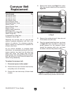
To replace the conveyor belt:
1. Disconnect power to the sander!
2. Remove the top cover (6 button head screws)
and pulley cover (4 hex bolts).
3. Remove the rear dust scoop (4 button head
screws).
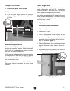
Conveyor Belt
Replacement
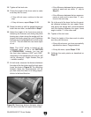
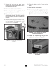
Figure 44. Drum sander disassembled
to Step 4.
4. Remove the V-belts (see Page 31 for help).
The drum sander should now look similar to
Figure 44.
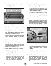
5. Remove the sanding drums (4 hex nuts and
4 flat washers on each one).
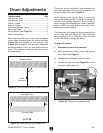
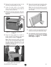
6. Place the gauge blocks face down, as shown
in Figure 45, raise the table to relieve the
spring pressure on the pressure rollers,
remove the pressure roller nuts, and lower
the table to remove the pressure rollers.
Figure 45. Gauge blocks set under pressure
rollers to relieve spring tension with the table.