


-24-
G0460/G0461 12" Sliding Table Saw
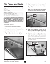
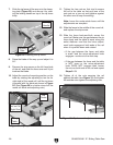
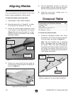
7. Slide the rip fence all the way onto the clamp-
ing plate
(Figure 29) and secure it by rotat-
ing the locking handle on top of the rip fence
body.
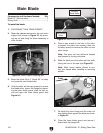
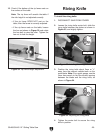
8. Raise the blade all the way up and adjust it to
90°.
9. Remove the stop screw on the left hand side
of the rail, and slide the fence over until it just
touches the blade.
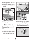
10. Adjust the round rail mounting position on the
table by rotating the adjusting nut on the far
right stud (of the round rail) until the rip fence
is parallel with the blade as shown in
Figure
30. (See Figure 26 for a better view of all the
round rail studs and adjusting nuts.)
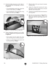
11. Tighten the hex nuts on that stud to secure
the rail to the table on that end (one of the
nuts acts as a jam nut and tightens against
the other one to keep the setting).
Note: Leave the center studs loose until the
adjustments are complete.
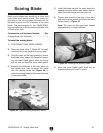
12. Slide the fence to the middle of the round rail,
and replace the stop screw.
13. Slide the fence back-and-forth across the
round rail. Make sure the gap between the rip
fence body and the table is equal along the
entire distance—and that the micro adjust
-
ment knob engages at both ends of the rail
when it is pushed down and rotated.
— If the gap between the fence and table
is even—and the micro-adjustment knob
engages—continue to the next step.
— If the gap between the fence and the table
is NOT even—or the micro-adjustment
knob DOES NOT engage—then loosen
the nuts on both ends of the rail and repeat
Steps 9–13
.
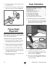
14. Tighten all of the nuts securing the rail
against the table (see
Figure 31) and tighten
the outside nuts against the adjusting nuts
.
Sliding
Table
Figure 30. Aligning the fence with the blade.
Rip
Fence
Adjusting
Nut on Far
Right Stud
Figure 31. Rip fence rail adjustment nuts.
Figure 29. Installing the rip fence.
Clamping
Plate
Locking
Handle