


G0605X/G0606X Extreme Series 12" Table Saw
-55-
Miter Gauge
Tools Needed Qty
Hex Wrench 2.5mm ...........................................
1
Phillips Head Screwdriver .................................
1
Machinist Square ...............................................
1
Adjustable Square .............................................
1
Wrench 8mm .....................................................
1
To adjust the miter gauge so it is perpendicu
-
lar to the saw blade:
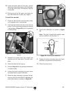
1. Slide the miter gauge into the miter gauge
slot to the left of the blade.
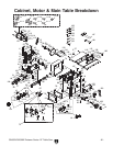
Figure 82. Example of fence aligned parallel to
miter slot.
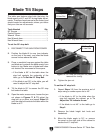
5. Loosen the jam nut and adjust the stop screw
until it is seated against the shaft (see
Figure
83 for part locations), then tighten the jam
nut.
6 Loosen the screw on the front of the miter
bar, adjust the pointer to 0°, then tighten the
screw.
7. To adjust to 45°, follow Steps 1-5 using an
adjustable square set to 45°.
8. Double-check your adjustments at 45° and
90° to assure that you have accurately set
your miter gauge.
9. To fit the miter bar tighter in the miter slot,
turn the adjustment set screws shown in
Figure 83 clockwise in small increments, and
test fit between adjustments until the miter
gauge fits your expectations.
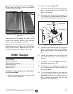
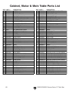
Figure 83. Miter gauge diagram.
Pointer
Jam Nut
Stop Screw
Shaft
Set
Screws
2. Push in the shaft (Figure 83).
3. Loosen the lock knob on the miter gauge and
place a square against the face of the miter
body and the blade.
4. Adjust the miter body until the pointer is at
0° and there is no space between the square
and the blade, then tighten the lock knob.
Lock Knob
Miter Body
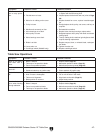
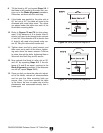
Place the fence alongside the miter slot (Figure
82) and check the fence to miter slot parallelism
and the clamping strength.
Trial-and-error will be needed to adjust the set
screws so the fence is parallel to the miter slot
and the clamping pressure is sufficient.
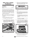
Optional: If you are cutting wet or green stock,
offsetting the rear of the fence
1
/64" from the blade
using the set screws in Figure
81 can help pre-
vent the workpiece from binding and burning.