


-4-
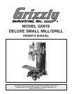
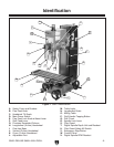
G0619 DELUXE SMALL MILL/DRILL
Main Specifications:
Spindle Travel ........................................................................................................................
2
3
⁄4"
Drawbar ....................................................................................................................
7
⁄16" x 20 TPI
Spindle Taper ...........................................................................................................................
R8
Swing ....................................................................................................................................... 18"
Longitudinal Table Travel .....................................................................................................
15
7
⁄8"
Cross Table Travel .................................................................................................................
5
3
⁄4"
Head Travel ..........................................................................................................................
14
7
⁄8"
Max. Distance Spindle To Column ............................................................................................
8"
Max. Distance Spindle To Table ..........................................................................................
14
3
⁄4"
Max. Drilling Capacity ...............................................................................................................
1"
Max. Tapping Capacity ............................................................................................................
1
⁄2"
Max. End Mill Capacity .............................................................................................................
1"
Max. Face Mill Capacity ............................................................................................................ 2"
Spindle Speed Range ........................................................................... 100-1750 RPM, +/- 10%
Quill Diameter ....................................................................................................................
2.362"
Table Info
Table Length ........................................................................................................................
21
5
⁄8"
Table Width ............................................................................................................................
6
1
⁄4"
Table Thickness .....................................................................................................................
1
1
⁄2"
No. of T-Slots .............................................................................................................................
3
T-Slot Width .......................................................................................................................
0.470"
T-Slot Height ......................................................................................................................
0.750"
T-Slot Centers .................................................................................................................
1-11/16"
Stud Size ..................................................................................................................................
3
⁄8"
Lead Screw Diameter ...............................................................................................................
5
⁄8"
Lead Screw TPI ........................................................................................................................
12
Lead Screw Length ................................................................................................................. 26"
Construction
Spindle Housing Construction ........................................................................................Cast Iron
Table Construction ..............................................................................Surface Ground Cast Iron
Head Construction .........................................................................................................Cast Iron
Column Construction ........................................................................... Surface Ground Cast Iron
Base Construction ..........................................................................................................Cast Iron
Paint ................................................................................................................................... Epoxy
Features
3-16mm Drill Chuck with Key R-8/JT-6 Arbor
Leveling Feet
Digital RPM Readout
Digital Milling Depth Readout
Digital Tapping Controls and RPM Adjustment
Tapping Direction Quick-Shift Buttons on Quill Levers
Manual Micro Depth Adjustment
Dovetailed Table Ways
Dovetailed Column Ways