-14- G8621 Heavy-Duty Sliding Table Shaper
Guard
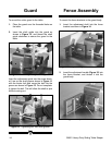
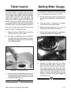
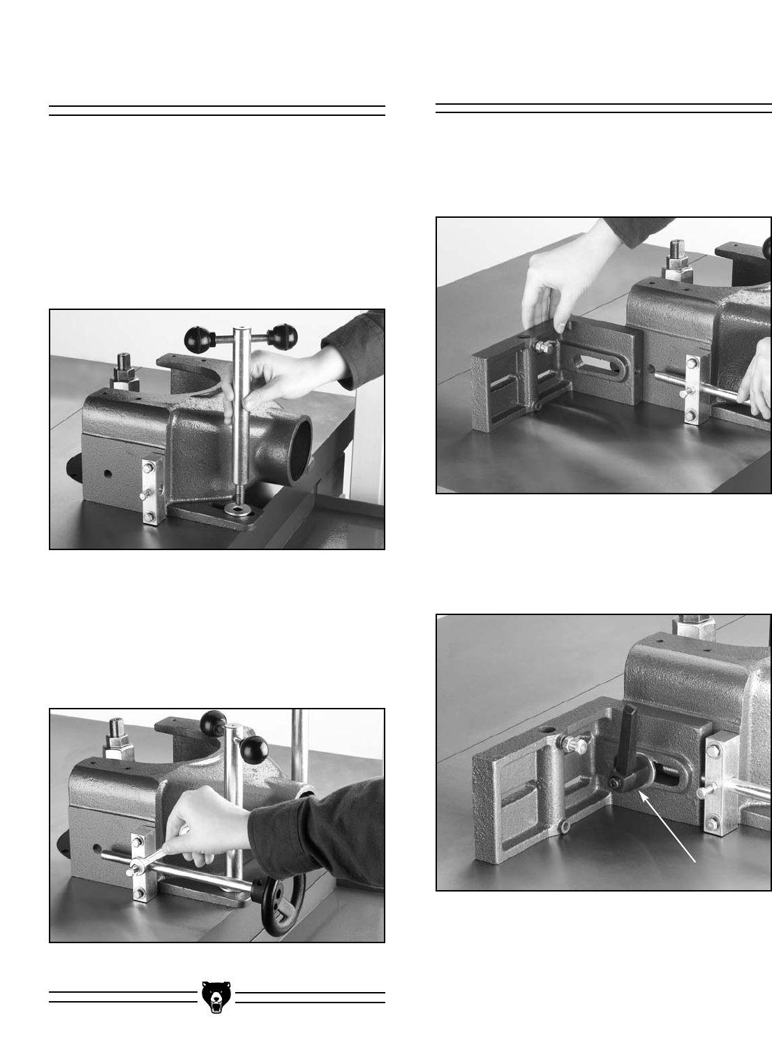
Figure 12. Inserting shaft guide into guard.
Figure 13. Tightening bolt into shaft groove.
Figure 14. Adjustment guide to fence bracket.
Figure 15. Adjustment handle.
Fence Assembly
To mount the fence brackets to the guard body:
1. Insert the adjustment shaft into the fence
bracket as shown in Figure 14.
2. Insert the adjustment handle (Figure 15) into
the fence bracket, and thread it into the
guard body.
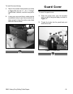
To mount the cutter guard to the table:
1. Place the guard over the threaded holes on
the table.
2. Insert the shaft guide into the guard as
shown in Figure 12, and thread the shaft
guide clockwise to secure the guard to the
table.
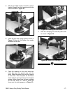
Insert the adjustment guide into the screw brack-
et. Line up the shaft groove shown in Figure 11
with the center bolt and screw the bolt into the
groove as shown in Figure 13. Do not complete-
ly tighten the bolt. This will allow the shaft to spin
without coming out.


