G8621 Heavy-Duty Sliding Table Shaper -29-
Freehand Shaping
About starting fixtures:
The purpose of the starting fixture is to support
the workpiece during the beginning of the cut.
The workpiece is typically placed in the starting
position using the starting fixture for support,
Then swung into the cutter while holding the
workpiece firmly against the starting fixture. After
the cut has been started, the work is swung away
from the starting fixture and is supported only by
the rub collar. Always feed against the rotation
of the cutter and do not start cuts at corners.
To use your pattern jig:
1. Remove the fence assembly. Choose the
appropriate cutter and rub collar for your
application and lock them in place. Secure
your workpiece to the pattern jig.
2. Check cutter rotation, and adjust the spindle
height to align the cutter to your workpiece.
Clamp a starting fixture to the table surface,
using the location that best supports your
work.
3. If everything is correct and the cutter is tight.
Turn the shaper on.
4. Place your jig/workpiece against the starting
fixture. Using firm pressure, pivot the work-
piece into the cutter and make sure the jig is
touching the rub collar. Keep your jig in con-
tact with the rub collar and slowly follow the
pattern, moving against the cutter rotation.
Freehand methods are one of the most dan-
gerous operations performed on a shaper.
Although this machine is capable of performing
freehand operations, we do not recommend that
you attempt to do so. If you MUST perform free-
hand operations, get formal training and read a
book that details freehand operations, their inher-
ent dangers, and ways to avoid those dangers!
Miter Assembly
When the workpiece is clamped to the table using
the miter assembly, crosscuts can be made with
a much greater degree of safety. The miter gauge
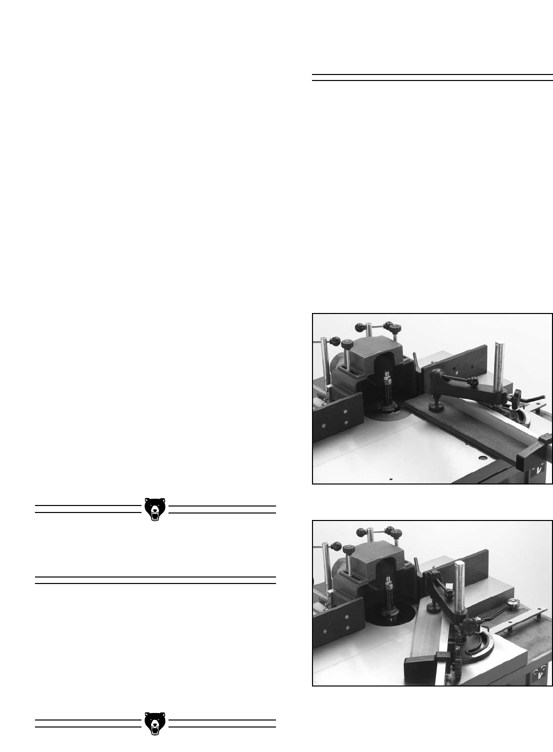
can be adjusted to 60° in both directions. Figure
43 shows the miter gauge set to 0° and Figure 44
shows it at 45°. To adjust the miter fence:
1. Loosen the miter gauge with the adjustment
handle.
2. Assuming that you have performed the steps
in the “Setting Miter Gauge” instructions, turn
the miter gauge in the desired direction so
the pointer indicates the angle, and tighten
the miter gauge with the adjustment handle.
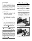
Figure 43. Miter gauge set to 0°
(fences opened for clarity).
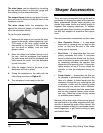
Figure 44. Miter gauge set to 45°
(fences opened for clarity).


