3650 Portable O2 Analyzer - Installation 11 of 50
Operator Manual
ORBISPHERE
1.6 Installation Completion Check List
1.6.1 Batteries
The instrument is designed to work on battery power. If battery power should drop, a LO
BAT warning appears in the instrument LCD's top-left corner, and they should be
replaced.
1.6.2 Instrument Clock Setting
If you use the instrument to store measurements for downloading to a PC, you should
verify the date and time settings of the instrument's internal clock, as described in “Clock
Settings” on page 39.
1.6.3 Electrochemical Sensor
Shipping conditions can have adverse effects on the sensor, thus you should perform a
sensor service as described in the accompanying EC Sensors - Maintenance &
Installation Manual before trying to make measurements.
However, if you intend to make trial measurements with the sensor as shipped, first
examine the sensor head. To do this, remove the plastic base at the bottom of the
sensor, then unscrew the calibration cap by loosening its collar (see “Electrochemical
Sensor Components - Exploded View” on page 8).
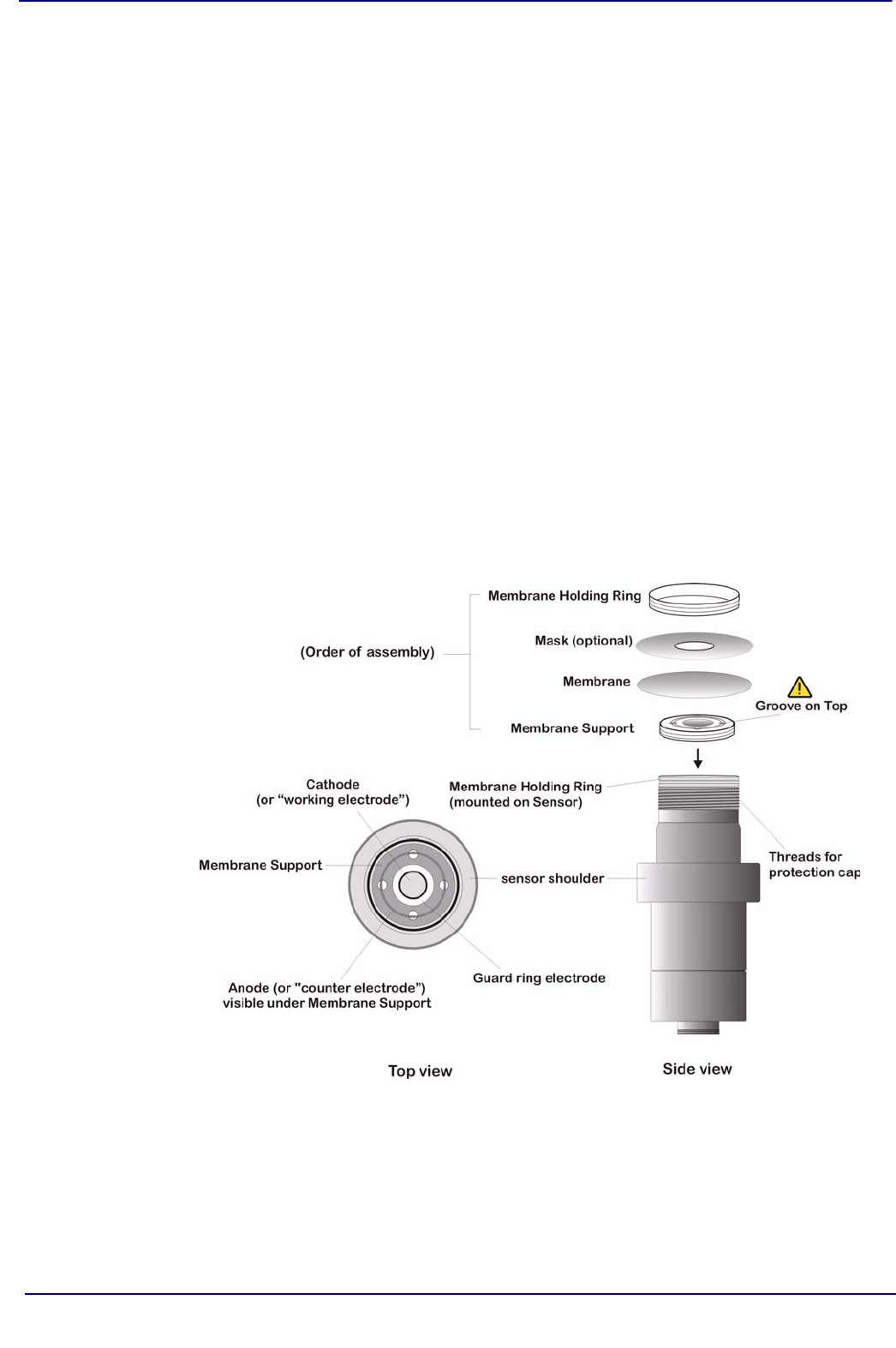
Your sensor head is fitted with a screw-on protection cap. For a view of the sensor head,
you must remove the cap, using the spanner key supplied in your recharge kit. Do this
carefully, making sure not to wrinkle the membrane that covers the sensor head, held in
place by a membrane holding ring. You should be able now to view the gold cathode in
the center, surrounded by a guard ring electrode, and separated by a fine groove. The
counter electrode is underneath the membrane support.
Fig 1-7: Sensor Components and Membrane Assembly Order


