


3650 Portable O2 Analyzer - Annex 47 of 50
Operator Manual
ORBISPHERE
Annex
Tables and Illustrations
Fig. 1-1 ORBISPHERE 3650 Portable O2 Analyzer.........................................7
Fig. 1-2 Electrochemical Sensor Components - Exploded View ......................8
Fig. 1-3 Flow Chamber 32007F........................................................................8
Fig. 1-4 32051 Sample Tube Adapter with Check Valve from Flow Chamber .9
Fig. 1-5 External Power Connection.................................................................9
Fig. 1-6 Instrument to PC Connections...........................................................10
Fig. 1-7 Sensor Components and Membrane Assembly Order......................11
Fig. 2-1 Instrument Front Panel......................................................................13
Fig. 2-2 Download Stored Values...................................................................18
Fig. 2-3 Sampling Point Descriptions..............................................................19
Fig. 2-4 Printed Sheet Information..................................................................20
Fig. 2-5 Clear Stored Values ..........................................................................20
Fig. 2-6 Real-Time Monitoring ........................................................................21
Table 2-1 Chart Updating Rate..........................................................................21
Fig. 3-1 Winlog97 Main Menu.........................................................................23
Fig. 3-2 Winlog97 File Menu...........................................................................23
Fig. 3-3 Winlog97 Logger Menu .....................................................................23
Fig. 3-4 Winlog97 Export Menu ......................................................................24
Fig. 3-5 Winlog97 Configuration Menu ...........................................................24
Fig. 3-6 Winlog97 Troubleshooting Menu.......................................................24
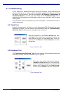
Fig. 3-7 Serial Port Configuration ...................................................................25
Fig. 3-8 Instrument Configuration ...................................................................25
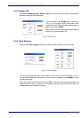
Fig. 3-9 Automatic Data Acquisition................................................................26
Fig. 3-10 Select Membrane ..............................................................................26
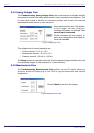
Fig. 3-11 Calibration Mode ...............................................................................27
Fig. 3-12 Lock Instrument CAL Button..............................................................28
Fig. 3-13 Calibration Range Check...................................................................28
Fig. 3-14 Span Gas Value ................................................................................28
Fig. 3-15 Dual Use............................................................................................29
Fig. 4-1 Pressure Calibration Screen 1...........................................................31
Fig. 4-2 Pressure Calibration Screens 2 & 3 ..................................................31
Fig. 6-1 Serial Link Test..................................................................................38
Fig. 6-2 Keyboard Test ...................................................................................38
Fig. 6-3 Display Test.......................................................................................39
Fig. 6-4 Clock Settings....................................................................................39
Fig. 6-5 Analog Input Test ..............................................................................40
Fig. 6-6 Measurements View..........................................................................40
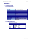
Table 7-1 General Technical Data.....................................................................41
Table 7-2 Instrument Display Options ...............................................................41
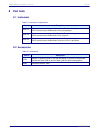
Table 8-1 Instrument Configurations .................................................................43
Table 8-2 Accessories .......................................................................................43
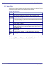
Table 8-3 Spare Parts Listing ............................................................................44
Table A-1 Common Units...................................................................................45
Table A-2 Terms and Definitions........................................................................45