


For technical questions, please call 1-800-444-3353;
Troubleshooting section at end of manual.
Page 12SKU 55525
TO ROUTE THE WIRE
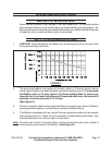
Note: When installing wire of different size or composition, you will also need to change
wire settings, set gun polarity, and, possibly, install gas cylinder. See pages 14-16.
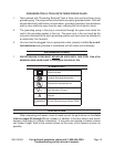
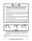
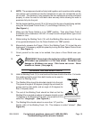
IMPORTANT: Securely hold onto the end
of the Welding Wire and keep tension on
it during the following steps. If this is not
done the Welding Wire will spring backward,
creating a tangled “bird’s nest” and resulting
in wasted wire. (See Figure D.)
Hold the Welding Wire securely while you
cut enough Wire off the end of the Spool to
remove all bent and crimped Wire. Make
sure the cut end has no burrs or sharp
edges (cut again, if needed). (See Figure D.)
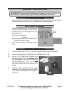
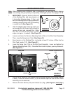
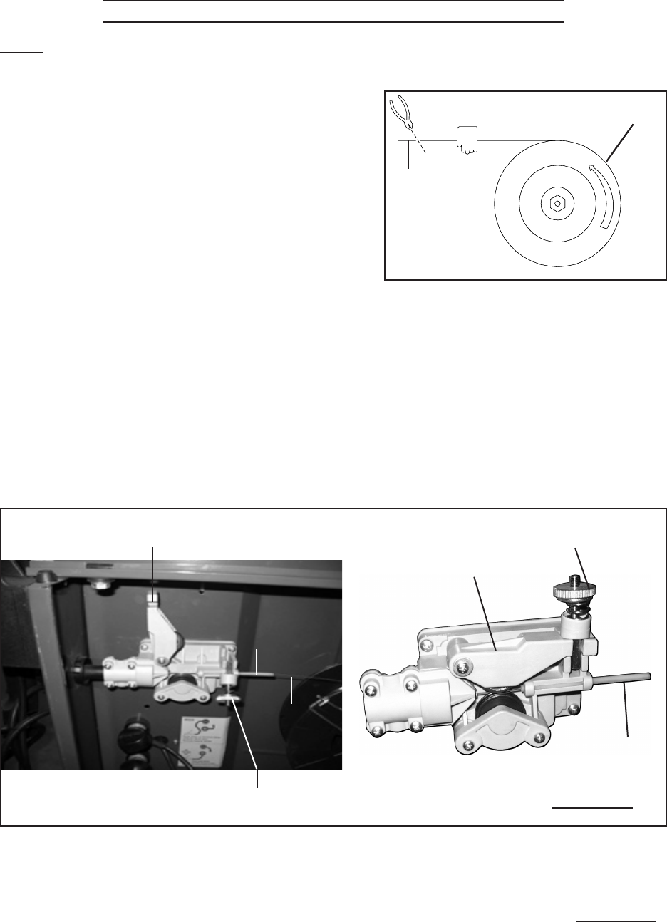
Loosen and lower the Tension Adjusting Knob (10b) on the Wire Feed Assembly.
Then, raise the Swing Arm (10a). (See Figure E.)
Keep tension on the Welding Wire, and guide at least 12 inches of Wire into the
Wire Feed Leader (10f). (See Figure E.)
Lower the Swing Arm (10a) on the Wire Feed Assembly. Lower and tighten the
Tension Adjusting Knob (10b). Once the Wire is held in place, you may release it.
(See Figure E.)
SWING ARM
(10a)
SWING ARM
(10a)
TENSION ADJUSTING KNOB
(10b)
TENSION ADJUSTING KNOB
(10b)
WIRE FEED
LEADER
(10f)
WIRE FEED
LEADER
(10f)
WIRE
FIGURE E
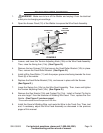
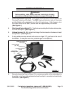
Lay the Torch Cable out in a straight line so that the Welding Wire moves through
it easily. Leave the Access Panel (12) of the Welder open so that the Wire Feed
Assembly can be observed.
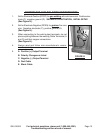
Remove the Gun Nozzle (15h) and Contact Tip (15g). (See Figure F, next page.)
1.
2.
3.
4.
5.
6.
7.
SPOOL
WELDING
WIRE
FIGURE D
SPOOL
WELDING
WIRE
FIGURE D