


For technical questions, please call 1-800-444-3353;
Troubleshooting section at end of manual.
Page 14SKU 55525
TO CHANGE WIRE SETTINGS
WARNING! Make sure to turn off the Welder and unplug it from its electrical
outlet prior to changing wire settings.
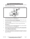
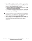
Open the Access Panel (12) of the Welder to expose the Wire Feed Assembly.
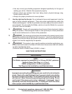
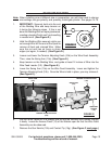
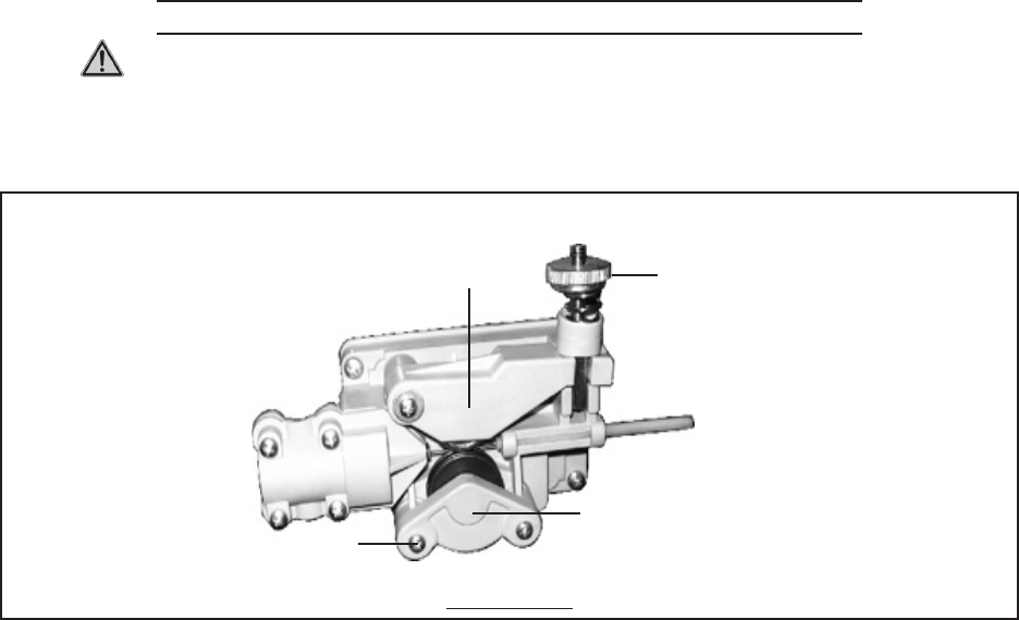
FIGURE G
SWING ARM
(10a)
TENSION
ADJUSTING
KNOB
(10b)
SCREW
(10l)
FEED
ROLLER
BRACKET
(10k)
Loosen, and lower the Tension Adjusting Knob (10b) on the Wire Feed Assembly.
Then, raise the Swing Arm (10a). (See Figure G.)
Remove the two Screws (10l) that secure the Feed Roller Bracket (10k) in place.
Then, remove the Feed Roller Bracket. (See Figure G.)
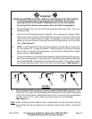
Install a Wire Feed Roller (11) with the proper groove size facing towards the Inner
Panel (8) of the welder.
Replace the Feed Roller Bracket (10k), and secure in place with the Screws.
(See Figure G.)
Lower the Swing Arm (10a) on the Wire Feed Assembly. Then, lower and tighten
the Tension Adjusting Knob (10b). (See Figure G.)
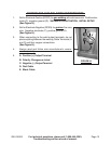
Remove the Gun Nozzle (15h) and Contact Tip (15g). Install a Contact Tip that is
one size larger* than the diameter of Welding Wire used. Then, replace the Gun
Nozzle. (See Figure F, previous page.)
*This accommodates thermal expansion of the wire.
Install the Spool of Welding Wire, and route the Wire to the Torch Gun. Then, test
and, if necessary, adjust the Wire Feed Assembly as discussed in the previous
pages of this manual.
1.
2.
3.
4.
5.
6.
7.
8.
9.