


SKU 93380 For technical questions, please call 1-800-444-3353. Page 19
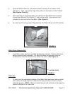
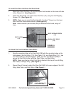
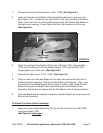
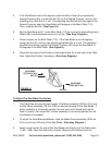
4. Temporarily remove the Table Insert (116A, 116B). (See Figure N.)
5. Insert the front tab of the Splitter (315) through the table insert opening in the
Main Table (115). Loosen the Hex Cap Screw in the insert opening in the Main
Table. Insert the front tab of the Splitter between the Flat Washer and Bracket in
the table insert opening. Finger tighten the Hex Cap Screw only at this time.
(See Figure N.)
SPLITTER (315)
TABLE INSERT
(116A, 116B)
FIGURE N
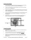
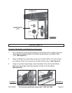
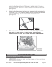
6. Attach the rear tab of the Splitter (315) to the L-Bracket (122), using one Bolt
(123), one Flat Washer (124), one Elastic Washer (125), and one Nut (126).
Finger tighten only at this time. (See Figure M.)
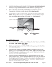
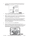
7. Reinstall the Table Insert (116A, 116B). (See Figure N.)
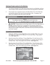
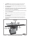
8. Check to make sure the Saw Blade will not come into contact with any part of
the Blade Guard Assembly. Position the Saw Blade at 90 degrees. Then, raise
and lower the Saw Blade through its full range of motion. Also, rotate the Saw
Blade,making sure the Blade never contacts any part of the Blade Guard
Assembly. Repeat this procedure with the Saw Blade in the 45 degree position.
9. Once the Blade Guard Assembly is properly adjusted, tighten all remaining loose
Bolts on the Assembly.
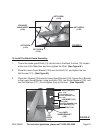
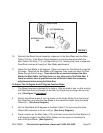
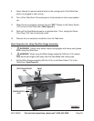
To Attach The Power Switch Assembly:
1. Attach the Power Switch Assembly (137) to the left end of the Front Rail (23B),
using two Screws (135).
(See Figure O,
next page.)