


Page 13SKU 97009 For technical questions, please call 1-800-444-3353.
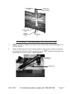
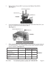
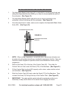
Setting up the Quick Vise an angle:
Remove Screws (A and B) from base of the Rear Vise Jaw (22).
Position (D) over (B) and attach the Screw and Washer (19 and 22) and attach Screw
(B).
Attach Carriage Screw (17) onto Slot (C) through the curved slot in the Base (1).
Align edge of the Rear Vise Jaw with the indexing rule and tighten Screws at (B and
C). (See Figure E.)
5.
•
•
•
•
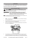
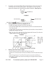
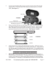
To operate, turn the Hand Wheel (5S) counterclockwise 1/2 turn and move the
Front Vise Jaw (9) to the desired position. Then tighten the Front Vise Jaw
against the workpiece by turning the Hand Wheel clockwise. (See Figure C.)
3.
FRONT VISE JAW (9)
REAR VISE JAW (22)
HAND WHEEL (5S)
HAND WHEEL (5S)
FIGURE C
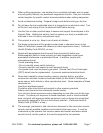
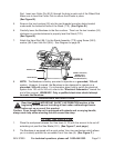
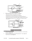
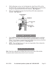
Setting up the Quick Vise for a straight (0°) cut:
Loosen the Screws (H) and (G) of Front Vise Jaw (F).
Turn the Hand Wheel (5S) counterclockwise by half a turn and slide back the
Front Vise Jaw (9).
Loosen Screw (A and B) and note that Screw (A) should be in the slot which is
parallel with the Rear Vise Jaw.
Rear Vise Jaw at the scale side should be aligned with the zero (0) on the rule.
Tighten Screws (A and B). (See Figure D.)
4.
•
•
•
•
A
B
C
22
D
9
FIGURE D
BASE (1)
G
H
ORIGINAL POSITION (FOR 0° CUTTING)
Note: Make
sure “C” slot is
free of casting
ush so the
vise can be
positioned in
all angles.