


Page 15SKU 91815
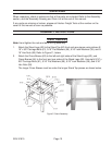
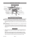
Assembling the Blade Guard and Splitter
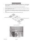
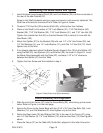
1. Insert the blade guard support Shaft (33) and Lock Washer (34) into the curved slot at
the rear of the saw Cabinet (57).
Screw in the Shaft clockwise using an open-end wrench until securely tightened. The
Shaft has a flat area for the wrench to fit. Refer to Figure H, below.
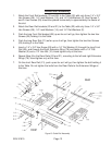
2. Thread a 7/16” Hex Nut (32) onto the Shaft (33), a little further than halfway.
3. Place on the Shaft (in this order) a 7/16” Lock Washer (31), 7/16” Flat Washer (30),
Bracket (28), 7/16” Flat Washer (30), 7/16” Lock Washer (31), and 7/16” Hex Nut (32).
Tighten the outside Hex Nut (32) so that the Bracket (28) is vertical (in line with the
Saw Blade (103).
4. Attach the Splitter (27) to the Bracket (28) with one 1/4” x 3/4” Hex Screw (29), two
1/4” Flat Washers (2), one 1/4” Lock Washer (31), and One 1/4” Hex Nut (12). Hand
tighten only at this time.
5. If not already attached, attach the Blade Guard’s Support Arm (26) to the Splitter (27)
using the Bolt (23), two Spacers (24), and the Nut (25), as shown in Figure H. Level
the Blade Guard assembly with the Table (22), and keep 1/16” to 1/8” clearance
between the Splitter (27) and the Table.
6. Tighten the Hex Screw and Nut installed in step 4.
Figure H. Blade Guard and Splitter Assembly
Fence Assembly and Alignment
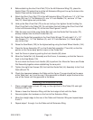
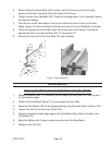
1. Slide the end of the Fence (37) onto the Fence Body (50), while lining up the screw
holes. Refer to Figure J, on the next page.
2. Secure the Fence to the Fence Body with four 5/16” x 3/4” Hex Cap Bolts (38), Lock
Washers (14), and Flat Washers (2). Hand tighten only at this time.
3. Attach the Rear Hook (35) and Sliding Pad (36) to the rear of the Fence (37) using
one 1/4” Flat Washer (2), 1/4” Lock Washer (14), and two Hex Nuts (12). See Figure H,
above.
4. Place the Fence (37) on the Table (22) Guide Rail, adjacent to the miter fixture slot.