


4
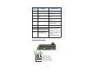
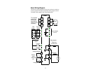
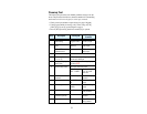
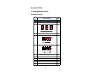
Basic Wiring Diagram
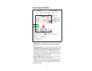
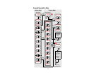
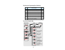
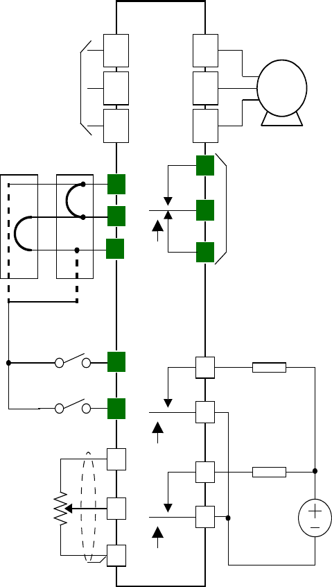
The following wiring diagram shows the power and motor connections
for basic operation. The optional signal input wiring supports external
Fwd and Rev Run command, and a speed potentiometer.
(L1)
R
(L2)
S
(L3)
T
(T2)
V
(T3)
W
(T1)
U
Motor
Forward
L
O
P24
PLC
CM1
ALO
AL2
AL1
5
FW
H
Reverse
Alarm contacts,
1 Form C
Run signal
Frequency
arrival signal
Relay outputs:
External
speed
reference
pot.
L300P
From 3-phase
power input
source (See
specifications
label on inverter
for details)
Load
Load
Analog common
Analog reference
11A
11C
12A
12C
–FU2/–FR
default
–FE2
default
Common
Inputs: