


OM-1594 Page 14
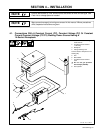
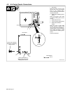
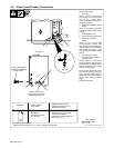
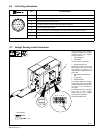
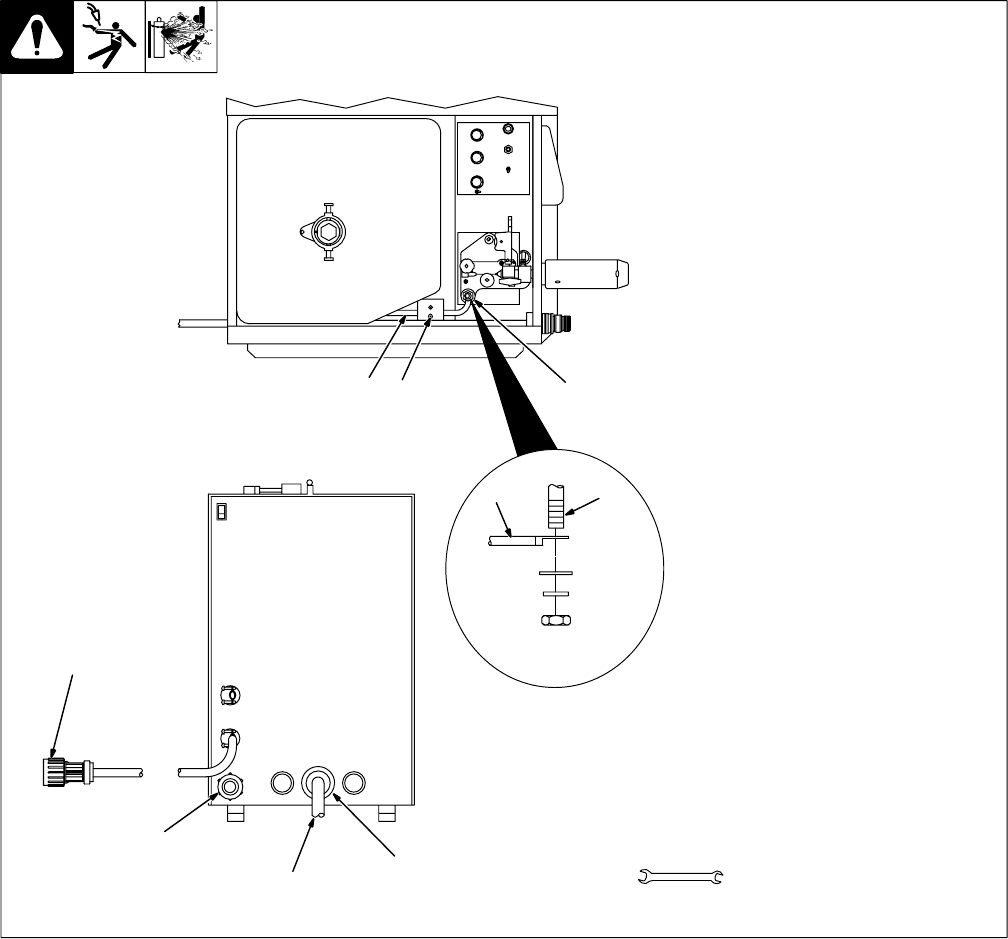
4-2. Air-Cooled Feeder Connections
Ref. 801 578-A
1 Gas Fitting
Route one end of 10 ft (3 m) gas
hose to rear of unit, and connect
hose to gas solenoid fitting.
Connect remaining end of hose to
regulator/flowmeter.
2 Weld Cable To Welding Power
Source
Select and prepare weld cable
according to welding power source
manual.
3 Weld Cable Grommet
4 Current Sensing (Reed) Relay
5 Weld Cable Terminal In
Feeder
Route one end of weld cable
through grommet, through reed
relay, and connect to weld cable ter-
minal in feeder. Connect remaining
end of cable to positive (+) weld
output terminal on welding power
source.
Close and latch door.
Tools Needed:
9/16 in
2
5
3
24
5
1
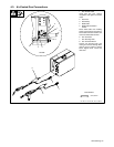
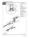
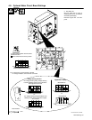
Rear Panel
Top View
Connect To Positive (+)
Weld Output Terminal On
Welding Power Source
Connect To 14-Socket
Receptacle On Welding
Power Source