


OM-1594 Page 16
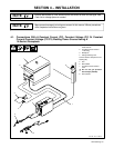
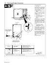
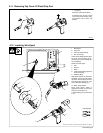
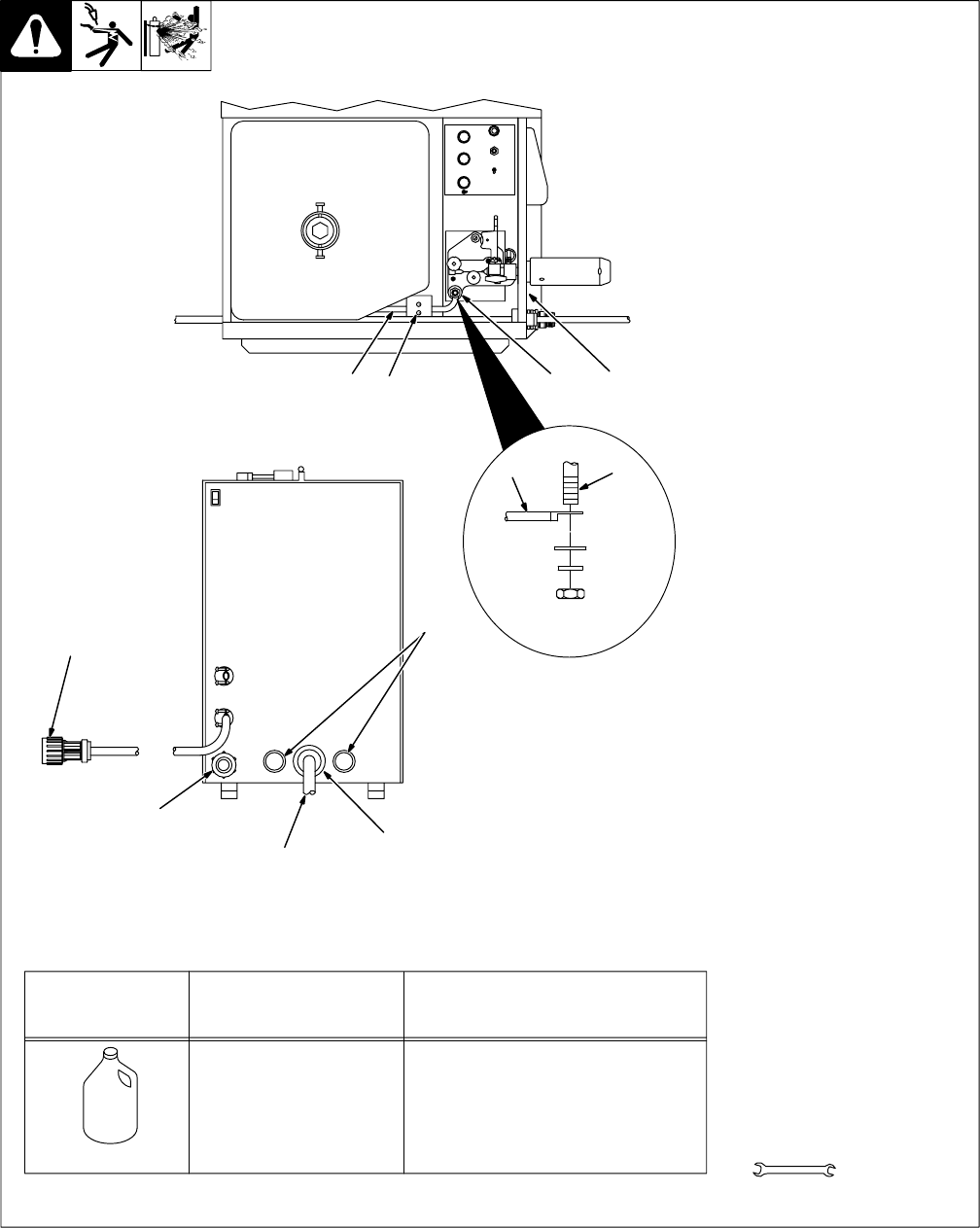
4-4. Water-Cooled Feeder Connections
Ref. 152 431-A / Ref. 801 578-A
Obtain coolant supply.
1 Gas Fitting
Route one end of 10 ft (3 m) gas
hose to rear of unit, and connect
hose to gas solenoid fitting.
Connect remaining end of hose to
regulator/flowmeter.
2 Weld Cable To Welding Power
Source
Select and prepare weld cable
according to welding power source
manual.
3 Weld Cable Grommet
4 Current Sensing (Reed) Relay
5 Weld Cable Terminal In
Feeder
Route one end of weld cable
through grommet, through reed
relay, and connect to weld cable ter-
minal in feeder. Connect remaining
end of cable to positive (+) weld
output terminal on welding power
source.
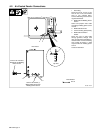
6 Coolant Hose Grommet
7 Location Of Coolant Fittings
On Front Panel
Route one end of a coolant hose
through grommet, and connect to
rear of Coolant Out fitting in feeder.
Connect remaining end to supply
fitting on coolant supply.
Route one end of remaining coolant
hose through grommet, and con-
nect to rear of Coolant In fitting in
feeder. Connect remaining end of
hose to return fitting on coolant
supply.
Close and latch door.
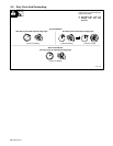
Tools Needed:
2
5
3
24
5
1
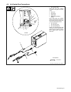
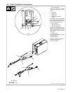
Rear Panel
Top View
Connect To Positive (+)
Weld Output Terminal On
Welding Power Source
Connect To 14-Socket
Receptacle On Welding
Power Source
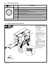
MILLER Low
Conductivity Coolant
No. 043 810**
MILLER Aluminum Protecting
Coolant No. 043 809**;
Distilled Or Deionized Water OK
Above 32° F (0° C)
GTAW Or Where
HF* Is Used
GMAW Or Where Coolant
Contacts Aluminum Parts Or
Where HF* Not Used
Application
*HF: High Frequency Current
**MILLER coolants protect to -37° F (-38°C) and resist algae growth.
Coolant
6
7
9/16 in