


OM-1594 Page 18
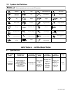
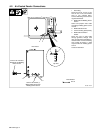
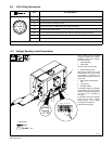
4-6. 14-Pin Plug Information
Pin* Pin Information
A 24 volts ac with respect to socket G.
B Contact closure to A completes 24 volts ac contactor control circuit.
AJ
K
I
G Circuit common for 24 volts AC circuit.
B
I
C
L
NH
C +10 volts dc output to remote control with respect to socket D.
C
NH
D
M
G
D Remote control circuit common.
E
F
E 0 to +10 volts dc input command signal from remote control with respect to socket D.
H Voltage feedback; 0 to +10 volts dc, 1 volt per 10 arc volts.
F Current feedback; 0 to +10 volts dc, 1 volt per 100 amperes.
*The remaining pins are not used.
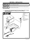
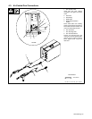
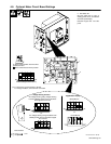
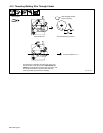
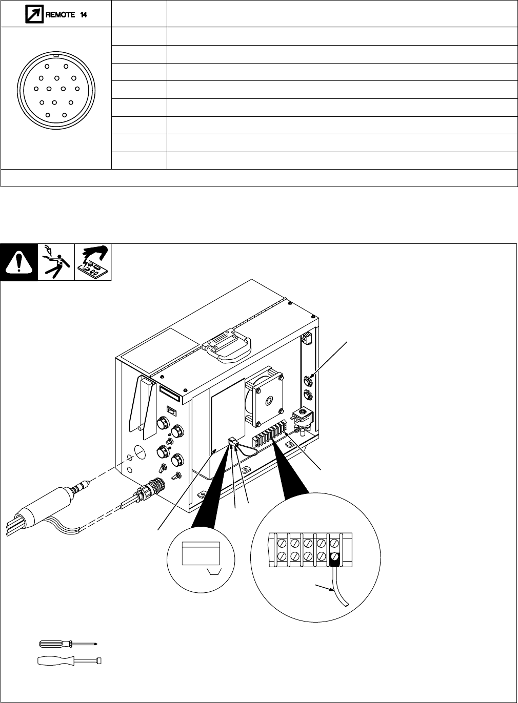
4-7. Voltage Sensing Lead Connections
801 557
Unit is factory set for constant
voltage (CV) welding. To set unit for
constant current (CC) welding,
proceed as follows:
1 Terminal Strip 2T
2 Strain Relief
Loosen screws of strain relief.
3 Voltage Sensing Lead
Route ring terminal end of lead
through strain relief, and connect
ring terminal to terminal A of
terminal strip 2T. Tighten screws on
strain relief.
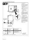
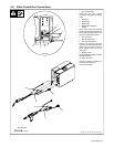
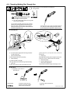
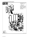
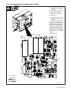
4 Motor Speed Control Board
PC1
5 Jumper Plug
6 Receptacle RC5
For constant voltage (CV) welding,
place jumper plug in INT. position.
Voltage sensing lead clamp does
not need to be connected to
workpiece.
For constant current (CC) welding,
place plug in EXT. position.
Connect clamp end of voltage
sensing lead to workpiece.
Reinstall right side panel.
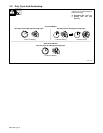
Tools Needed:
1/4 in
EDC BA
3
4
EXT INT
RC5
321
6
5
1
2