


13
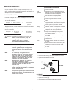
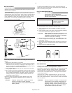
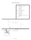
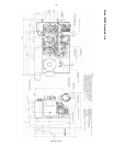
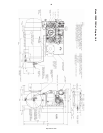
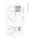
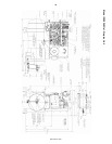
ELECTRICAL WIRING DIAGRAMS
A To supply
C Wiring for optional electric drain valve
EDV Electric drain valve
T Supply Line Terminal
L Load Terminal
FU Control Circuit Fuse
HATS High Air Temperature Switch (#)
LOLS Low Oil Level Switch (#)
M Motor Starter Coil
OL Motor Starter Overload
PS Pressure Switch
SS Selector Switch (#)
* Alternate wiring for converting 3 phase starter to
1 phase application
(#) = if provided
Three Phase Wiring
NOTE Connect line power to the starter. Do not connect line power to the
pressure switch.
•
Connect ground wire to ground lug
Starter
To Power Supply
SS
SS
S
SS
SS
S
http://air.irco.com