


6
PRESSURE SWITCH ADJUSTMENT
aWARNING High voltage is present at the pressure switch
contacts when the power supply is
connected. Disconnect, lock and tag main
power supply before making adjustments.
aCAUTION Do not adjust the pressure switch to exceed
the maximum discharge pressure of the unit.
NOTE Adjust the pressure switch only if
adjustments are absolutely necessary.
CUT-IN & CUT-OUT. The cut-out (compressor shut-down) is the
pressure at which the switch contacts open, and the cut-in (compressor
restart) is the pressure at which the switch contacts close.
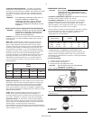
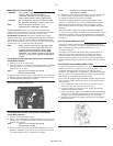
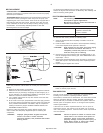
ADJUSTMENT CONTROLS. All pressure switches have a range
adjustment control (A). Some pressure switches also have a differential
adjustment (B) control. On switches without a differential adjustment
control, the span between cut-in and cut-out pressure levels switches
is factory set for 40 ± 4 PSIG and cannot be adjusted.
NOTE Some pressure switches are equipped with
an on-off lever used to open and close the
electrical contacts inside the switch. THIS
LEVER IS NOT A DIFFERENTIAL ADJUSTMENT
CONTROL. The pressure switches with the on-
off lever do not have a differential adjustment
control.
ADJUSTMENT PROCEDURES (SWITCHES WITHOUT DIFFERENTIAL
ADJUSTMENT CONTROL):
1. Remove the pressure switch cover.
2. Adjust the range by turning the range adjustment screw clockwise
(in) to increase the cut-out point or counter-clockwise (out) to
decrease the cut-out point.
NOTE: One full turn changes the setting
approximately 2 PSIG.
3. Replace cover, reconnect power supply and start the compressor.
4. Note the pressure gauge reading at which the compressor cuts out.
5. Repeat adjustment procedure if necessary.
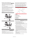
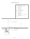
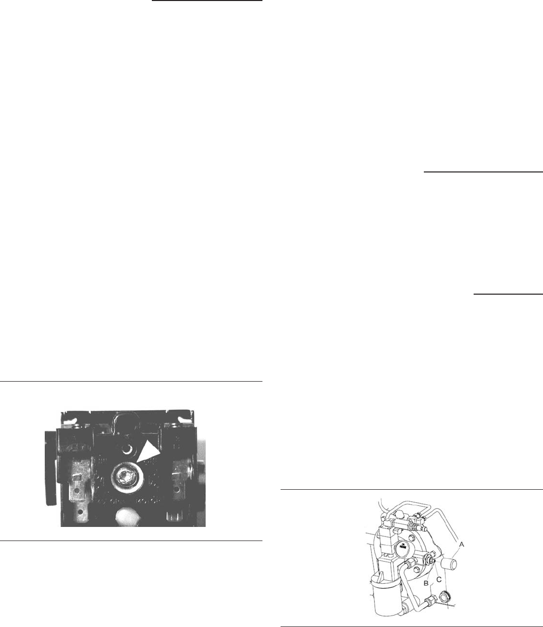
Pressure Switch Range Adjustment
ADJUSTMENT PROCEDURES (SWITCHES WITH DIFFERENTIAL
ADJUSTMENT CONTROL):
1. Remove the pressure switch cover.
2. Set the cut-in pressure with the range adjustment nut. Turn the nut
clockwise (in) to increase the pressure or counter-clockwise (out) to
decrease the pressure.
NOTE: One full turn changes the setting
approximately 2 PSIG.
3. Set the cut-out pressure with the differential adjustment. Turn the
differential adjustment nut clockwise (in) to increase the pressure
or counter-clockwise (out) to decrease the pressure.
NOTE: One full turn changes the setting
approximately 2 PSIG.
4. Replace the cover, reconnect the power supply and start the unit.
5. Note the pressure gauge reading at which the unit cuts out.
6. Repeat the adjustment procedure if necessary.
The minimum possible differential is approximately 20% of cutout
pressure. It is advisable to have as wide a differential as possible to
avoid frequent starting and stopping of the unit. Note the pressure
gauge reading at which the unit cuts-out and re-establish this point if
necessary.
Note the interaction between the range and differential adjustments,
i.e., if the cut-out is increased, the differential will also increase, or if the
differential is narrowed, the cut-out will be reduced, etc. These factors
must be considered when adjusting the switch and compensated for
accordingly.
ELECTRIC DRAIN TIMER SETTINGS
The "time off" setting determines the interval between cycles from
30 seconds to 45 minutes. The "time on" setting determines the actual
time the compressor drains condensate from the 1/4" or 1/2”
condensate outlet port.
The timer’s cycle rate and drain opening time should be adjusted to
open just long enough to discharge the condensate. The timer is
properly set when it opens and discharges condensate and then
vents air for approximately one second before closing. Adjustments
may be made depending on many factors, including humidity and duty
cycle.
OIL PRESSURE ADJUSTMENT (MODEL 2000P)
For pressure lubricated compressors, the oil pressure should be
checked upon start-up by observing the oil pressure gauge. The
acceptable operating range is 15-40 psig. It is normal for the oil
pressure to vary slightly with oil temperature. Compressors equipped
with an optional low oil pressure shutdown system will automatically
shut down if the oil pressure drops below 10 psig.
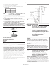
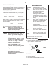
The oil pump is equipped with an adjustable pressure regulator which
may be reset if conditions warrant. Refer to the following illustration
and instructions:
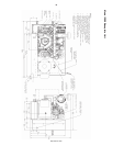
1. Use an adjustable wrench to remove the knurled cover for the
valve on the right side of the oil pump housing (A).
2. Loosen the retaining nut (B) with a 7/16” wrench such that the
threaded rod (C) is free to rotate.
3. Using a 1/8” hex key, adjust the threaded rod to the desired setting.
Turning the rod clockwise increases the oil pressure setting, and
turning the rod counterclockwise decreases the oil pressure.
4. When the oil pressure is set, tighten the retaining nut and replace
the knurled cover.
http://air.irco.com