


10
2. Re-tighten the set screw with your fingers
until it only lightly touches the column tube.
3. Hold the set screw in position with the hex
wrench, and re-tighten the hex nut.
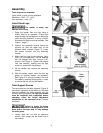
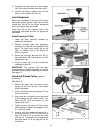
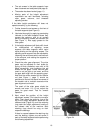
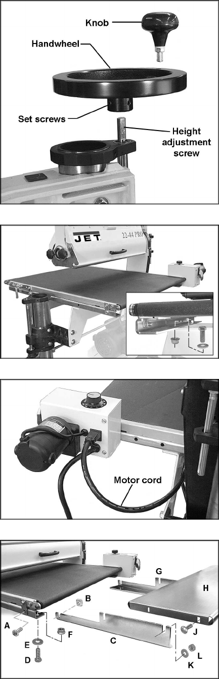
Install Handwheel
Mount the handwheel to the top of the height
adjustment screw (Figure 6). Align one of the set
screws with the flat on the height adjustment
screw, and tighten both set screws.
Install the knob to the threaded hole in the
handwheel, and tighten the hex nut against the
handwheel.
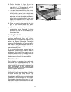
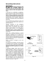
Install Conveyor Table
1. Lower the table mounting brackets by
rotating the handwheel.
2. Remove conveyor table from packaging,
and place it on the mounting brackets of the
stand. The gear motor should be on the
right, or inboard side of the sander as
shown in Figure 7.
3. Secure the conveyor bed with four 3/8”x1”
hex head bolts, 3/8” flat washers and 3/8”
flanged lock nuts.
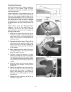
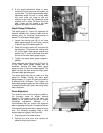
4. Plug the motor cord into the control box
receptacle (Figure 8).
IMPORTANT: The conveyor belt has been
overtightened for shipping purposes. It must be
tensioned properly before operating the sander!
See page 19.
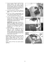
Infeed and Outfeed Tables (Optional
Accessory)
See Figure 9.
1. Remove the lower hex cap screw (A) and
square nut (B) from the rail on the infeed
side of the sander.
2. Slide a left hand mounting bracket (C) into
the end of the rail.
3. Align holes and re-install the hex cap screw
(A) and square nut (B). Install a 3/8”x1” hex
head bolt (D), 5/16” flat washer (E) and
flanged lock nut (F).
4. Tighten the hex cap screw (A) first to align
the bracket, then tighten the flanged hex nut
(F) on the 3/8” screw.
5. Install a right hand mounting bracket (G) in
the same manner. NOTE: You will have to
o
pen the control box to remove the screw
from the rail – remove the front lower screw
and base panel (# 16 on page 38) of the
control box.
Figure 6
Figure 7
Figure 8
Figure 9