


17
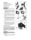
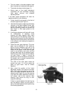
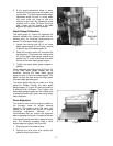
6. If one height adjustment screw is loose,
remove the miter gear from the transfer rod
on that side. Turn down the threaded height
adjustment screw rod until it is snug. Make
sure both sides are snug on top and
retaining rings under the adjustment screw
supports are in place. Re-install the miter
gear. Loosen the set screws in the table
supports and test for smooth operation.
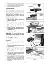
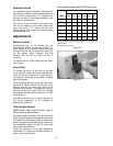
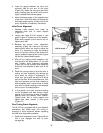
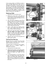
Depth Gauge Calibration
The depth gauge (A, Figure 25) measures the
distance between the conveyor table and the
sanding drum for thickness dimensioning of
boards. To calibrate the depth gauge:
1. Loosen the locking knob (B) of the lower
depth gauge support (C) and lower it so that
it rests on top of the table support (E).
2. Raise the conveyor table until it touches the
sanding drum. Then loosen the locking knob
(D) of the upper depth gauge support and
position the “0” mark of the scale even with
the top of the lower depth gauge support.
3. Tighten the upper depth gauge support in
position.
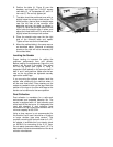
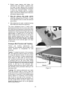
Once calibrated, the locking knob (B, Figure 15)
of the lower depth gauge support can be
loosened, allowing the lower depth gauge
support to ride on top of the table support. The
depth can then be read where the scale enters
the lower depth gauge support.
The depth gauge can also be used as a stop
gauge as follows: Position the lower depth
gauge support (C, Figure 25) along the scale to
a desired finish thickness. Then tighten the
lower depth gauge support with the locking knob
to prevent the conveyor table from being raised
above that point.
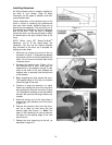
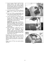
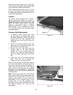
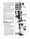
Drum Alignment
The sanding drum must be aligned parallel to
the conveyor table for proper machine
operation. The sanding drum has been pre-
aligned at the factory and should not require
immediate adjustment, although it is
recommended that you confirm the alignment
before operating the sander. Proceed as follows:
First inspect the alignment with a gauge of some
kind. The following procedure uses a steel
straight edge as a gauge. See Figure 26.
1. Unplug sander from power source.
2. Remove the dust cover and remove the
abrasive strip from the drum.
Figure 25
Figure 26